6SN7 / 6CG7 preamp

GroupDIY Audio Forum

Help Support GroupDIY Audio Forum:

This site may earn a commission from merchant affiliate links, including eBay, Amazon, and others.

rafafredd

Well-known member
Joined
Jun 3, 2004
Messages
2,412
Location
Rio, Brazil
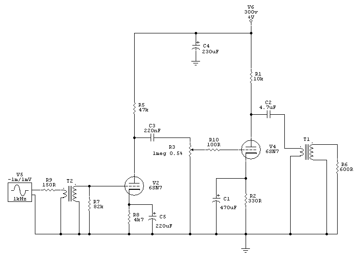
Here is another one of my new drawings. After some years of DIY, I´m starting to draw some tube circuits. as it´s always a pleasure to share, here it is.
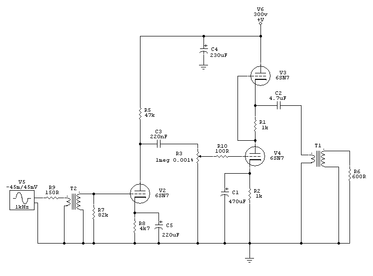
6CG7_mic_preamp.gif


The 6SN7 and 6CG7/6FQ7 are cheap tubes and most of you might have many on the bench. I do have many. This is a no overall feedback design, that uses just three tubes for a stereo unit. I think this is a clever use of triodes.

A simple 2:1 transformer would make for the output, or you could use no transformer at all, if you don´t need to drive heavy loads. This will give some more gain. So, any 2k4:600Z, 2:1 ratio will do. You can also use the common "line split" 600:600+600 types, wired as 2:1 ratio, inverted, primary in series.

For the inputs, I recomend 1:5 to 1:15, depending on how much gain you need. 1:7 to 1:10 are probably the best alternatives.

As you see, this is a very simple desing, but criticism from the masters, and also from newbies, by the way, is most welcome.
 
Only learning myself, so nothing to add yet. Except that this is a GREAT thread ! Ill be watching closely :grin:
 
I had just been poking at a much more complicated many-tube mike-amp; yours is elegant.

> The 6SN7 and 6CG7/6FQ7 are cheap tubes

6SN7 has become Collectable. Try 12SN7. Try the toy 6SN7: the 12AU7.

Reduce the pot value. 1Meg, not even counting wiring capacitance, will give -1dB at 16KHz when set to 50% or -6dB. 250K will work.

Is "0.001%" the pot setting? That is not realistic. A lin pot can be set down to 5% or 3%, an audio taper pot can be set down to 0.5% or so. This will matter for output level and distortion estimates.

With 2:1 output transformer, gain from first grid to 600 ohm load is almost 26dB. Add 1:10 input iron, 46dB.

Same but 10K load, 36dB from first grid to load (56dB with 1:10 input iron).

That 10dB drop with loading suggests what I expected: this stacked output is not a low impedance. It is around 1,200 ohms at the load, 5K at the tube. In fact it is about the plate impedance of two 6SN7 working together. The top tube is NOT a cathode follower, and we do not get the ~500 ohms expected from a CF. If you want a low-Z output, you want the White Cathode Follower. Yes, it is unity-gain instead of gain=15: that's the trade-off.

In a way this is "good". Your C-L output coupling rings at about 20Hz. With a zero-Z source, the ring can be tremendous. I could not get any significant rise out of this plan, confirming that it is hi-Z and won't let the C-L network ring.

However, output UNloaded, you get a 20Hz ring that shorts-out the output tube, and THD will rise.

I'd make that first plate resistor larger. Not for gain or output, but so it eats less current and B+ filtering is cheaper. If we assume we want buzz below hiss, 0.2uV hiss before the transformer is 2uV after the tranny and 20uV at the plate. PSRR is 6dB-10dB, so 40uV ripple on the first stage B+. If we assume 1V ripple at the main filter cap, we need 88dB ripple reduction! Disdaining all sand-state devices, or the heat and dubious performance of vacuum regulators, we need 3 or 4 more R-C sections to get the B+ clean enough for the first stage. Large input stage current means low-R resistors which means hi-C hi-$ caps. (This may not be a big deal at today's cap costs.)

The main "failing" that I see is that, at mid-band, it will hardly make +18dBm in 600 ohms at clipping. 6dB below clipping, THD is like 4%. In 10K load it can make 20V rms at clipping, OK.

If the top tube is replaced with 10K resistor, and bottom output tube cathode resistor reduced to 330 ohms: gain is 27dB into 600, 35dB into 10K. And it gives +21dBm at clipping. Actually -lower- output impedance and higher output power! Not much, but you save one tube, one heater, one above-ground heater that could break-down, and no downside except double the B+ drain.
 
PRR, your circuit analyses is just great!

Is "0.001%" the pot setting? That is not realistic.

Yes, it was.

Maybe this is a circit where regulted B+ would be nice.

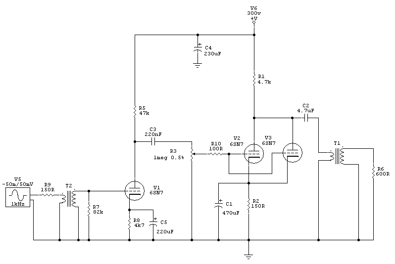
I´ve worked on two more drawings, based on your last post:

6CG7_mic_preamp_2.gif


6CG7_mic_preamp_3.gif


First one became a 6SN7 or 6CG7 one bottle! I know what you mean about those getting collectible, but it only apply to the 6SN7 family, not the 6CG7/6FQ7.

Simulator is really not so happy with the first one driving a 2k4 load, but I believ in you MUCH more than this sucky simulator.

The second one is to drive a 2:1 2k4:600Z transformer easier. Would this work???

If I may ask... what do you think overall now?
 
I am no tube guru, but if you can spare two tubes per channel you could make the first stage that mu-amp you used for output in your initial circuit. Then borrow Jakob's SRPP output and just plug in that 6CG7. You could play with anode/cathode resistors to your liking. If you use cathode bypass resistor you should be able to get 17dB gain and near -20dB PSRR in the first stage.
 
Yeah. I see your point TK. But I really would like to do it all with just three bottles for two channels, or maybe, as PRR suggested, just two bottles for two channels, that´s one bottle for channel. Really nice!

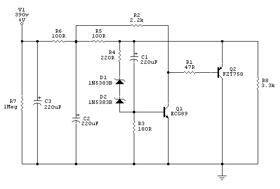
Here is my first try on a sand state regulator for this thing. I know I still do have to get some resistor values right. But here is a first schem, just to get the idea:

regulator.gif
 
Even two sides of a 6SN7 in parallel won't be happy driving 2.4K at higher levels. I'd use a 4:1 output, then try to make up the extra 6dB of loss somewhere else... perhaps use 1/2 6SL7 for the input stage, one side for each channel. And there's your three-bottle, two-channel preamp.

The level pot doesn't need to be 1M, and such a large value will cause high frequency rolloff, looking into the grid of the following stage. A good rule of thumb is that for maximum output, the following grid resistance--in this case, the pot--should be at least four times the value of the plate resistor of the stage preceding it. But since you're trying to pass full bandwidth audio, you want to make that pot as small as you can without causing excessive loading of the preceding stage.

Don't put a lot of faith in those tube models in Circuitmaker. They tend to predict better performance (especially with large signals) than what you'll get in real life. Diddling around with a simulator is fun, but it's no substitute for real design work.
 
[quote author="rafafredd"]
Here is my first try on a sand state regulator for this thing. I know I still do have to get some resistor values right. But here is a first schem, just to get the idea:
[/quote]

You will probably want some output cap on this---be sure to include a realistic series R for the ESR of the real cap when you do sims. Otherwise it's a pretty decent shunt reg topology once you fine tune the series R values for your particular current drain. It's not going to be too tolerant of abuse as it stands, particularly in regards to the peak fault currents in the transistors (can you say PAFFFF goes the silicon?). Be mindful of zener dissipation too.

Agree with NYD on the spice tube models in circuitmaker---waaay optimistic most of the time.
 
Even two sides of a 6SN7 in parallel won't be happy driving 2.4K at higher levels. I'd use a 4:1 output, then try to make up the extra 6dB of loss somewhere else... perhaps use 1/2 6SL7 for the input stage, one side for each channel. And there's your three-bottle, two-channel preamp.

mmm. If I would use a 10k primary, I would probably try a single triode driving it. Do you think a half 6SN7 / 6CG7 would do it?

If yes, I would arrive into a very nice design, just one bottle for channel, easy to get tubes, enought gain for most uses, low heater power needed, low parts count, very simple to build, level control with regular log pots, from 0 to max with 600 Z output for driving anything from tape machines to semi-pro level inputs.. If you need more gain, I´ll include a switch at the output for driving unbalanced high Z loads directly, with 12dB more gain.

If the one bottle concept will drive the 10k output iron nicely, I may get crazy and try to put eight channels of those into a 1U rack enclosure, with an out of the box PSU, obviously...

I have many beyer 1:15 comming, so maybe I could use those for getting more gain at the first stage, instead of 1:7 transformers, and still use the 6SN7 / 6CG7 tubes...

The level pot doesn't need to be 1M, and such a large value will cause high frequency rolloff, looking into the grid of the following stage

Yeah, I´ll try a 220k pot. PRR told me about it in his post above, but I forgot to include this mod in my first redraw. Thanks for the heads up.

Don't put a lot of faith in those tube models in Circuitmaker. They tend to predict better performance (especially with large signals) than what you'll get in real life. Diddling around with a simulator is fun, but it's no substitute for real design work.

Yes, I know about CM tube models, and all. I´m actually trying to do like the dead man did, looking into tube curves and using formulas, but it´s the first time, so it´s stil very easy for me to get confused with all the parameters, formulas and curves. I´m not taking the simulation so serious this time.

It's not going to be too tolerant of abuse as it stands, particularly in regards to the peak fault currents in the transistors (can you say PAFFFF goes the silicon?).

Argh! I´m really not a fan of these high voltage discreet regulators. They do it all the time and I rate when they do it, like paffff...

I´m just trying to get low ripple without a choke and all those big caps.

Any easy way to make it more PAFFFF PROOOOF ?

Be mindful of zener dissipation too.

Yes, the idea is to use three or four in parallel for summing dissipation and get high voltage reference without having to import zeners from Germany or England. I´m thinking local stores...
 
Shunt regulators make sense only when load current is near-constant and input voltage is near-constant. Here, load current is moderately well controlled (except when tubes are cold!) but input may vary wildly.

Otherwise, you have to waste way too much heat in the regulator. And heat is already an issue in a tube amp.

A 2-stage amp does not need decoupling for stability, but you need super-clean B+ at the first stage, not-so-clean in the second stage. Since the second stage eats much more current, you probably want an R-C decoupler between stages to lessen cap size/cost.

Do you really need 600 ohm load performance? If not, don't even try. A 12AU7 and 10K:10K will drive most modern inputs well.

If you must whack 600 ohms, you either need to flow DC in the output transformer or you need a bigger tube than these. 6EM7 is one of many low-price dual-tubes tubes with large sections. There was a series of dual dissimilar triodes in early USA TV design. In areas where TV was allowed to mature before it became common, triode-pentodes serve the V-sweep function, and these could be run triode-strapped for similar duty.
 
Do you really need 600 ohm load performance?

Not always, but many times yes. I have three new (old) varimu compressors in the studio now, and also some old and very nice EQs. All of them true 600 ohms inputs.

If you must whack 600 ohms, you either need to flow DC in the output transformer or you need a bigger tube than these.

So, this is my answer. I´m contacting guilherme tomorrow for a gapped version of his 10k:600 transformer. He is an expert in high inductance, low resistance transformers. very high quality, according to my test. I can´t say enought good things about this guy. he knows what he does. I do think he can make a gapped version with high enougth inductance if I push him a little. His non-gapped version has a 10k primary inductance of 285H, althought measured in low level, but it´s high anyway!!! I think it´s like 160H or more in full level. So, if it falls a little in a gapped version he probably can add more turns, and the core is already very big, very good quality brazilian grain oriented M4.

How much maximum current should I ask him to flow throught the primary? Only 10mA at 300v is enought?

Better to invest money in a good iron, done by a local guy, and keep it one-bottle (low heater power), tubes I have many, low parts count.

For the PSU I´ll think about a simple RC filter, specially now that I´ve decided about the gapped trafo for the second stage. An extra filter for the first stage, that will be running at 250v with a high drop of 50v in this extra filter.
 
Before you invest in custom iron, try this. It might meet your needs well enough, and uses a regular (non gapped) 10K:600 output.

ForRafa1.jpg


B+ is 300V, well-filtered but not necessarily regulated. R1 represents the secondary impedance of the input xfmr, R11 and R12 represent the voltage stepdown of the output xfmr. I don't use the transformer models in Circuitmaker because they don't seem to work very well.

Electronic gain is about 42dB, or 30dB to the secondary of the output xfmr. With a 1:10 input xfmr, you'd have 50dB total, or 53dB with a 1:15 input, etc.

THD is below 1% at normal operating levels--IF you believe the simulator.
 
"ForRafa.jpg"?

Dave, you are a gentleman, and a brilliant guy!

I´ll try it in the next days and let everyone knows how it went, here in this thread, with pictures. The Preamp case is ready, with tube sockets and all. PSU will be out of the box.
 
I spent an hour looking for a classic two-triode broadcast mike amp schematic. Where are they hiding?

> very good quality brazilian grain oriented M4

That's what the plan wants, to drive 600 ohms.

10K is a bit low for best performance from 6SN7-like tubes. It will give maximum voltage gain, but high THD and high output impedance.

Assume tube Mu is 20 and plate resistance is 10K. If we load it with 10K:600 4:1, the tube gain is (10K/10K+10K)*20= 10, times 4:1 is 2.5. Output impedance is 600 ohms: good if you live in a matched world but not so great in the real world.

Now load it with 40K:600 8:1, the tube gain is (40K/10K+40K)*20= 16, times 8:1 is 2.0. Zout is 150 ohms, low enough that loading hardly changes output voltage.

Maximum gain and output comes with matching, but full output tends to be 5% THD or more. Higher impedance load reduces THD much faster than it reduces power. Typically we load a triode in 2 to 5 times plate resistance for good power with low distortion. For a real 6SN7 this suggests 15K to 40K.

10mA at 300V is a possible bias for transformer coupling. A good loadline would swing to 15V 15mA and 450V 5mA. That's 30K load, 750mW peak, 375mW RMS, and looks like 2% THD. Peak voltage in 600 ohms is 20V. We'd normally never need half that, so THD may be below 1% at studio peak level.

The primary impedance does not HAVE to be 30K. It has to be higher than the 8K plate resistance. 100H may be enough.

> low resistance transformers.

Low DCR is not a real benefit here. If it is as high as 3K, the output resistance rises a bit, and you need 10% more supply voltage, no huge deal.

Perhaps the biggest problem is: how small a wire does he want to work with? If he is set up for power and speaker transformers, he may not have very small wire, or have trouble winding a lot of it.
 
mmm... I have some 15k:600 transformers here that I may give a try on the NYDave circuit. It will probably work a little better than the 10k:600...

About the gapped one, I´ll have a talk with guilherme. He does work with 42 and 44 AWG wire.
 
I agree with PRR about higher primary Z being better for loading a triode. If you have 15K:600, use 'em. It's only 2dB more loss.

PRR: two-triode broadcast preamps don't seem to be as common as pentode-input, triode-output circuits. But here's a couple I found in my files. Thanks to the people who scanned and posted them originally.

http://www.groupdiy.twin-x.com/albums/userpics/10031/Collins6Q1.jpg
http://www.groupdiy.twin-x.com/albums/userpics/10031/RCABC2BPreamp.jpg
 
No, it's 10K.

There was a period--up till sometime in the '50s, by my reckoning--during which "M" was used sometimes to mean a thousand ohms. M is the Roman numeral for a thousand. Now, of course, we use K (Kilo) for a thousand, M (Mega) for a million. Needless to say, this can cause some confusion when looking at these old schematics! Luckily, you can usually figure it out from the context.
 
> If you have 15K:600, use 'em. It's only 2dB more loss.

Not even 2dB. Coming up from a near-match, the voltage gain rises almost as fast as the step-down.

For 6SN7 transfromer-coupled:
10K:600 _ gain to plate=11.1 _ gain to output=2.77
15K:600 _ gain to plate=13.04 _ gain to output=2.61
0.516dB drop

For 6SN7 resistor-loaded with 10K then transformered:
10K:600 _ gain to plate=8 _ gain to output=2
15K:600 _ gain to plate=8.9 _ gain to output=1.78
1.02dB drop

Note, in the Collins 6Q1 plan, that the 10K plate resistor is "decoupled" with 1uFd and 5K6. This gives a slight rise below 50CPS, probably offsetting transformer droop. Note also that the first stage decoupling resistor is as big as the plate resistor.

A key difference between these industrial preamps and (what I think) rafafredd is going for: feedback. You want to be able to swap-out a sick preamp in the middle of a show and not change program levels. Not so important in small studio work.
 
Yes, I really want no overall feedback this time. First because I never explored tube no feedback designs, so I don´t know how it sounds. Many hifi people advocate that it siounds better, althought it measures higher distortion most of the time. Second reason, is that I don´t want to fight with gain control, feedback caps, need for input and sometimes even output pads, etc... Start with the simple. I want a simple, cheap and intuitive volume control! You can also drive anything from consumer to pro levels. Third is less options, good sound, more fun recording.
 
Back
Top