flickinger cards???

GroupDIY Audio Forum

Help Support GroupDIY Audio Forum:

This site may earn a commission from merchant affiliate links, including eBay, Amazon, and others.

buschfsu

Well-known member
Joined
Dec 31, 2004
Messages
760
Location
jacksonville FL
so i have a friend with 10 flickinger 290-3 cards. since they are probably custom i tried to trace the schematic using guesses based on spectrasonics 101 and 110 schematics.  ( note the polarity on the tats was left out.oops)  Anyway couple questions....

what the hell are those clear/white things?
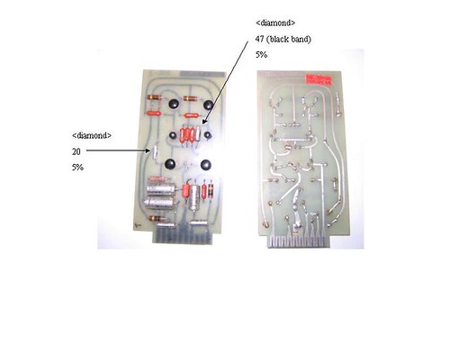
One checks out as a diode (has a diamond with 47 and 5%) has a black band on one end and read .67v
other has a diamond and a 20 with 5% but doesn't appear to be a diode or cap or resistor?  i don't have a clue?

next question.  anyone have a pinout for a perfectly round TO-105?  there doesn't seem to be a way to differential C from E?

anyway i tried to trace the card and any feedback would be appreciated.  I want these done right!!!
2420611949_334287563a.jpg


UPDATE: I used a 50k pot.  worked better than the 10k. Als used 2n5210 for the npn's and 2n5087 for the pnp's.  matched hfe on the input npn pair. they sound great.


:grin:
 
I suspect they are polystyrene caps and are 47pf and 20pf values.
A bigger photo link would help, but I,m 99% sure thats what they are.

Marty.
 
Curious ?

used a cap checker ? uf or nf ?

5% - usually resistor or cap, not a diode

i could be wrong but it looks like axial tants or styrene
commonly seen it discrete cards like this.
 
If the outside shell is metal it's probably an axial tant. But if its a clear plastic shell (with a taper or bevel at the ends) it's a polystyrene cap. Also, many axial 'styrenes have one lead off-center on the cylinder end. You should also be able to see some of the spiral wrap structure through the ends if it's 'styrene. A close-up macro photo would help.

A P
 
ok ill take pictures. i really don't think 47 is a cap. it its black on one end and reads .67v like a diode would. the 20 has no black band and doesn't read anything on the diode meter.

any comments on my trace of the circuit?
 
> a pinout for a perfectly round TO-105?

The TI Epoxy transistors have a flat-spot on the circular rim. Fondle it a while, you will feel it.

Also the three legs are not an equilateral triangle.

> any comments on my trace of the circuit?

It would aid defuddlement to un-wrap it so input is on the left, output on the right, rails top and bottom. I know what it is but I can't recognize it in your trace.

And 2N4249 is PNP, not NPN.... no wunda your maze makes no electrical sense.

> i really don't think 47 is a cap. it its black on one end and reads .67v like a diode would

If you read in-circuit, there is probably a "diode" across it some how. If you un-soldered one end of a polystyrene cap carelessly, you may/may-not have melted its guts (though that would usually read "zero").

Try this thread, which references an older thread (Dec 2004) which I can not find. Also this thread which has text-snips and a lot of missing links.

flickinger-S-V.gif


top view, flipped:
flickinger-T.jpg


flickinger-B.jpg
 
> 10 flickinger 290-3 cards. since they are probably custom

The world was full of them. It is a shame that today's studios are tiny, and those old consoles are cut-up.

Dan Flickenger was quite a guy: http://en.wikipedia.org/wiki/Daniel_Flickinger

George Massenburg:
"Parametric EQ... In my informed opinion only four people could possibly lay claim to the modern concept:
Bob Meushaw, Burgess Macneal, Daniel Flickinger, and myself" http://www.massenburg.com/cgi-bin/ml/parametric_invention

Unsubstantiated chit-chat: http://recforums.prosoundweb.com/index.php/t/4418/0/

Somebody was soming something: http://www.pastemagazine.com/action/article/1467/feature/music/the_kills
 
i have flick cards too. i'll try and post a pic of mine, if y'all are interested? mine came with a hand drawn schem, which i could scan, if it'd be helpful to anyone...

now, anyone wanna tell me what would be the most "historically accurate" xfmers to use with the flick cards would be? i'm guessing UTC's? i realize i may be opening a can of worms here...
 
Flickinger blueprints I've seen use custom flat-pack PCB mount Triad transformers.
 
[quote author="PRR"]George Massenburg[/quote]

Some very funny bits in that piece:

"It's [sic] pathetically intelligence-challenged chief exec, Jack Best, imagined himself to be a visionary captain of industry (Jack had slipped some cash to Spiro Agnew - remember him? - in trade for a position on the CAB), and was producing and distributing business programs on cassette."

"Incidentally, during that time I was taking Electrical Engineering at Johns Hopkins University, a school that was as medieval, apathetic and oppressive as schooling in the 60's could get. I got into a row with a 'professor', who looked at a schematic for a gyrator that we had built and declared it "of theoretical interest only", and "impractical" to implement. Seeing this as a sign, I dropped out of college. "

"Some years later I came to the aid of...was it Bill Thompson of Ashley Audio? Ray Dolby's attorneys were trying to "mine" the Dolby circuit patents and levy a fee of...geez what was it? 5c per band for a 1/3rd octave EQ's? I had previously implemented the circuit that Dolby engineers had patented in 1976; it is fundamental in the implementation of "reciprocal" curves. Luckily, it was described in an ITI manual which predated Dolby's patent, thus establishing "prior art". "

Whew. A nickel per third-octave! That's EVIL :twisted:
 
I think I originally posted the pics that PRR put up here (that was about two computers ago, so I forget.) Anyhow, the iron on those was UTC O-12 on the input & A-20 or A-22 (some 600:600 or other) on the out. That info might be in the old info PRR linked to--I can't remember.

Tom
 
[quote author="hodad"]I found 2 things mundox (originator of the original thread) sent me--http://home.comcast.net/~giuseppe_poteet/IMG_2178.JPG
which shows xformer connections & edgecard pinout.
and

http://home.comcast.net/~giuseppe_poteet/flick_Attenuator.jpg

which is a U attenuator for use with this preamp, I believe.

I may have more of the old thread stashed away somewhere. I'll have a look.[/quote]

wow! that's great! any more info you could post would be fantastic!

i will take pics of my card ASAP so we can maybe build a "flick database" of sorts on here, cuz it's so dang hard to find correct info on the flick stuff... :green:
 
i will redraw my schematic to be more readable (1st attempt at a trace!!) but thanks for all the input (looking at you paul). ill let you know how this progresses. im racking a two channel 1st with carnill (neve) xformers on in and out. Im sure ill have questions about attenuation and the feedback pin. (my guess is to feed the output into the feedback pin with a 10k audio taper pot)

thanks all. yes a flick dbase is an excellent idea. Ill keep this updated
 
i will be taking pics of my cards tomorrow and post them then. i know that bill scibbe has a flick board up and running and he knows a LOT about flick stuff. is he here on the prodigy board? anybody? bueller? :wink:
 
[quote author="emrr"]Bill is the guy, but he can be hard to get ahold of, like any busy guy.[/quote]

yeah, i talked to bill via e-mail a few years ago and he gave me some good info, however, my computer died not soon after and that info got lost in space, as they say... :mad:

is he actually a member of this board?
 
spoke with bill for about an hour regarding these cards. very cool... tons of history around these things.

also i removed my initial attempt at a trace thanks to PRR. not sure about C5 and C6 polarity though.
 
I'm actually looking at a console right now that it purported to be a Flick. I've had a few people question it's authenticity and a few vouch for it.

Anyone have any additional pics of Flickinger consoles that might help to verify things?

I'm particularly interested in seeing pics of the card cages, etc.

Thanks,

Riv
 
if you can look at the pcb's, they may say Flickinger on them. The board that PRR posted has it, it's just cropped out of the picture.
 
Back
Top