12 input balanced sum amplifier DIY project

GroupDIY Audio Forum

Help Support GroupDIY Audio Forum:

This site may earn a commission from merchant affiliate links, including eBay, Amazon, and others.
MikeFFG said:
but how do you go about wiring the other side of that?  Say to 12 TRS cables.  You just plug all the grounds into that one pin?  Would that not get a little crowded lol?

It is a common practice to connect the shield of a balanced line at one end only. If you have e.g. XLR connectors at the other end, it is easier to ground the shields there.

MikeFFG said:
what would be the difference in sound between this and a passive one?

Depends on the design, but generally passive summing adds more noise and color. This circuit is transparent and very low noise compared to passive alternatives.
 
audiox said:
MikeFFG said:
but how do you go about wiring the other side of that?  Say to 12 TRS cables.  You just plug all the grounds into that one pin?  Would that not get a little crowded lol?

It is a common practice to connect the shield of a balanced line at one end only. If you have e.g. XLR connectors at the other end, it is easier to ground the shields there.

MikeFFG said:
what would be the difference in sound between this and a passive one?


Depends on the design, but generally passive summing adds more noise and color. This circuit is transparent and very low noise compared to passive alternatives.


right right.  Ground at one end.  I don't know why I didn't think of that.  Thanks for the response.  Do I want more color or less noise? hmm maybe I'll just have to build both!
 
I love the design of this!

What would I leave out to make it passive, or alternatively, is there a way to keep the design the same but tap the signal somewhere earlier to get a "passive output" as well, (a la the XSum)?

Say for instance to run through my pres for make-up gain, to add that "color"??
 
To use this passively, Place R1-25 and R28 as shown. Jumper from the 'input' side of R26 to the 'output' side of R29. Jumper R30 'input' to R32 'output'. This gives you a Passive Summing mixer that is either balanced, or stereo unbalanced!

Values for these are given by the formula: R=(N-1)/(N+1)xZ where N is the number of channels, Z is the desired impedance, and R is the resistor value! Note that if you are using it balanced though, you should half this resistance value you calculate... For more info, see anything by NYD on passive summing, in the Meta thread... (That's where most of the above info came from...)

If you want to get creative with switching I think you could Passive and Active Summing with one PCB, but for the cost of the switch you may as well just build both... There's not £10 worth of components in there (not counting the PCB, of course!!).

Also worth noting that the active version cant be used stereo unbalanced without cutting a trace or two, and omitting an opamp and a couple of resistors. Not sure how this would affect balanced operation though, OTOH...

Mo
 
COOL, thanks!!

I guess I wasn't paying close enough attention, I didn't even notice it was a single balanced output, LOL.

So, really for balanced stereo operation, you'd be building two of these circuits in one box running side by side? Which would give you 24 ch?

Or, doing what you described, when you have 2 unbalanced outputs, could you balance them with a trafo at some point? Or just not bother?
 
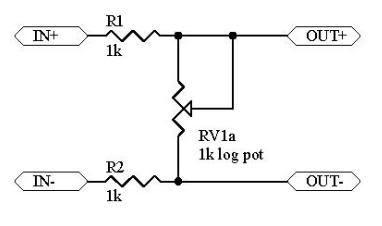
So what if I threw in this on the front end?

BalancedPad.jpg


With this H pad on the front end it seems as though this works as a balanced summing mixer with volume control?

Any thoughts?

CC
 
What's the best way to add a volume control to the output of this? I'd like it to be switched, should I just put a rotary switch with different values in place of R28 and R31?
 
benlindell said:
What's the best way to add a volume control to the output of this? I'd like it to be switched, should I just put a rotary switch with different values in place of R28 and R31?

Remove R27 and make R28 variable.

Sorry about the late answer.
 
The original google pages sites seem to be lost - does anyone have backups of schematics, PCBs layouts etc.?

Thanks in advance
 
This is all wayback would give up... Missing the layout values file....
 

Attachments

  • SUM-12_copper_mirror_image.pdf
    21.2 KB · Views: 17
  • SUM-12_layout_designations.pdf
    7.8 KB · Views: 1
  • SUM-12_schematic.pdf
    12.8 KB · Views: 2
  • SUM-12_wiring.pdf
    16.3 KB · Views: 2

Latest posts

Back
Top