Active summing bus/output section for mixing console

GroupDIY Audio Forum

Help Support GroupDIY Audio Forum:

This site may earn a commission from merchant affiliate links, including eBay, Amazon, and others.
Thanks for the troubleshooting suggestions!!

It'll be a couple days before I can get back to work on this.  Its a huge relief to be making headway.

I'll test methodically to see exactly where the low end roll off is occurring. 

I need all the basic help I can get...  thank you.

 
Okay....I got this circuit to work a couple weeks ago... both channels.  Thank you to all who posted, especially John Hardy for looking at the schematic and noting that it should work.

I just wanted to post about the sound, it is much clearer & cleaner than my previous IC based summing bus.  So this has been a worthwhile project as my mixes sound richer and there is more of a depth of field.  The low mids are stronger.  My EQ's sound less harsh(even though they are stock/unmodified).  When I am looking at a test signal using a sweep generator and a scope and to my uneducated eye I don't see any weirdness.

There are still a couple issues, I'm 600 miles away from the board right now, so I can't test, but in the next week or so I can get back on it.

What is not shown on my posted schematic is where the audio signal branches off to the monitoring section of the board.  This occurs after the last output 990 but before the output transformer.  I have to use an unbalanced cable to connect the output of the board (output transformer secondary) to get the correct, flat low end.  So the unbalanced cable is shorting the Lo to ground, and it can be just a dummy plug not interfacing with any other equipment so I can get the correct low end to monitor.  It sounds like a classic phase issue to me, no low end with a bit of upper mid distortion.  The phase on the patch bay looks fine on the scope as well as the signal I run into the board and post-output transformer output are in phase.

so maybe the monitoring section wants to see the (pre-output transformer) internal phase reversed?  This is my poor electrical skills talking....but I was surprised that shorting the output transformer's secondary would affect the signal pre-output transformer.

When I use my unbalanced "workaround" I am confident in the signal's integrity.  I'm very pleased with the sound.

 
I have to use an unbalanced cable to connect the output of the board (output transformer secondary) to get the correct, flat low end.  So the unbalanced cable is shorting the Lo to ground, and it can be just a dummy plug not interfacing with any other equipment so I can get the correct low end to monitor.  It sounds like a classic phase issue to me, no low end with a bit of upper mid distortion.  The phase on the patch bay looks fine on the scope as well as the signal I run into the board and post-output transformer output are in phase.
The output signal of the transformer exists on the ORN and YLW wires. Wherever you send the signal, regardless of whether it is a balanced input or unbalanced input, BOTH of those wires must be used. Otherwise, you do not have a complete circuit. Were you trying to use just pin 2 and pin 1 of the XLR as the output? If so, you don't have the complete output circuit, and it will sound wrong (if it sounds at all).

John
 
I understand that the ORN & YLW wires both need to be used, but this is a good point.  Next week when I get back to the console I'll test to make sure the signal is actual getting from the ORN & YLW to their respective Hi & Lo outputs on the output channel connectors. 

The tricky part is that I'm using the original summing bus circuit board with the new parts soldered point to point on a daughter board, so there could be complications interfacing the two.  The output connectors are on the original board.

Thanx!
 
Hi everybody!
It's an old post, but i've got a similar problem.

Setup:
I'm updating the master section of a soundcraft TS-12, with a 990C and Jensen transformer as seen here:
http://www.jensen-transformers.com/as/as026.pdf
It's powered by +-16V (stays stable) and I only use 1 ground from the ground rail (for 990C, and trafo in/out).
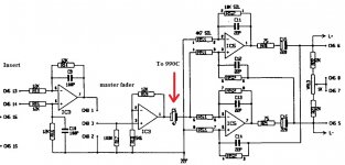
I tapped off the signal after the master sum and insert. I cut the traces of the "old" master output section, so it wouldn't interfere.
The output of the trafo goes to the patchbay, and to the control room circuit.

Problem: There is a low shelf, sub frequencies are much lower. After a few minutes, there is a upper mid distortion, that gets worse in time, and the highs seem to disappear (at first they were beautiful, better than the old master setup).

I'm wondering what's going wrong here. Any input is welcome!!

the picture is of the left master section, from insert. I took out the condesator where the red arrow is, and placed it on a sub board, with the 990 and the tranny's
 

Attachments

  • master left.jpg
    master left.jpg
    73 KB · Views: 46
for easy looking at the setup, here is the output setup with the 990 and the jensen transformers
 

Attachments

  • 990C jensen output.jpg
    990C jensen output.jpg
    55.7 KB · Views: 45
Hmm, I now see that the Jensen design has a gain of 12 dB, while the "old" output, had a gain of 6 dB.
The IC(3 and 4) after the master insert, also has a gain of 6 dB, thats a total of 18dB, instead of 12dB.

I could reduce the gain of the post insert IC to 0 dB, by removing the 5k6 Ohm from - to ground, and adding a 22P bypass cap over the 12K from - to output. (correct?)

This way, the gain only happening at the 990C and is back to 12 dB.
 

Attachments

  • lessgain.png
    lessgain.png
    19.8 KB · Views: 7
I had contact with John Hardy, he was so kind to explain, that the non inverting input of the 990C had no reference to ground, because of my 220uF coupling cap of the preceding stage.
He also pointed out that a simple voltage divider could do the trick of reducing 6 dB, by using equal size resistors.

Al my setup already has a 249 ohm resistor between the non inverting 990C input, and the 220uF coupling cap,
I want to put in a 249 ohm resistor to ground after it.
 

Attachments

  • master left.jpg
    master left.jpg
    25.5 KB · Views: 28
I put in the mods today, and it works beautiful. I ended up using 2x 1k8 ohm as a voltage divider (6dB) and kept the opamp after the master fader intact.
I don't need the 24V, it has plenty of headroom.
Job well done, with many thanks to John Hardy who helped me out.
 

Latest posts

Back
Top