Tube P.Transformer - elevated secondaries, why ?

GroupDIY Audio Forum

Help Support GroupDIY Audio Forum:

This site may earn a commission from merchant affiliate links, including eBay, Amazon, and others.

maxwall

Well-known member
Joined
Nov 17, 2004
Messages
1,134
I finished a 5F1 guitar amp build that looked to be a easy and fun project and I can't figure out why the power transformer secondaries are so high.

Its passing audio fine.

Dealing primarily with hum issues and a new speaker crackle , but I think the speaker crackle may be due to elevated dc voltages on tubes plates etc.

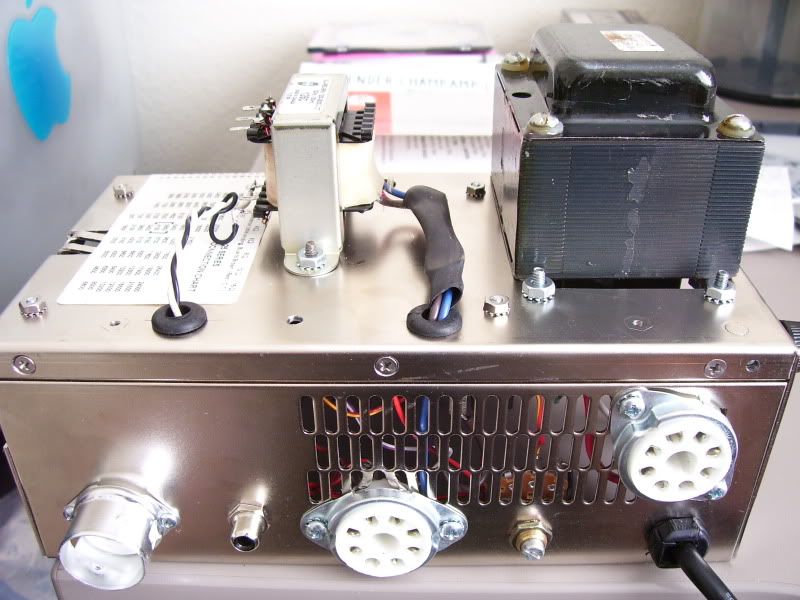
The transformer being used is a New Sensor NSC125P1B
specs 325-0-325(650vct) 70ma, 6.3v 2a, 5v 2a

line voltage 60hz @ 122 vac measured with dmm


seconadary - measured
HT 351-0-351 ( ~700vct ) ??? Much too high.....
heaters 6.9vac no center tap - easily fixed with a 1 ohm dropping resistor
rectifier heater 5.3vac - not terribly worried about this one.

the elevated HT secondaries are jacking up voltages all over the circuit by as much as 50Vdc

Here are voltages on the output and preamp tubes

6V6- voltages
pin 3 (plate) 402vdc
pin 4 (grid2) 363vdc
pin 8 ( cathode ) 20.62vdc

12ax7- voltages
pin 1 (plate1) 216vdc
pin 6 (plate2) 211vdc
pin 3 (cath2) 1.45vdc
pin 8 (cath1) 1.27vdc

5y3 - voltages
pin 4-6, 351vac on each leg ( approx 700 vac, should be 650 vac) a bit high , may need a dropping resistor here.
pin 2-8, 5.3vac
pin 8 to first filter cap 16uf/475 cap is 409 vdc

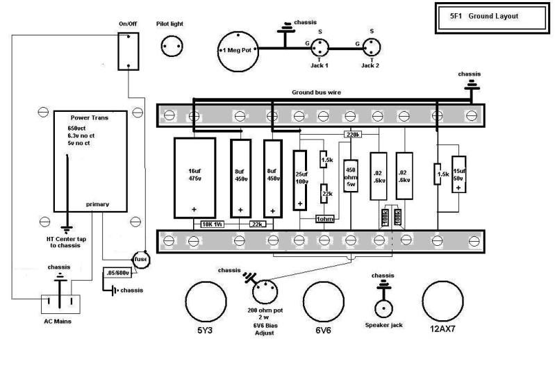
here is the original 5F1 schematic

http://img.photobucket.com/albums/v611/maxwall/5f1_layout.jpg

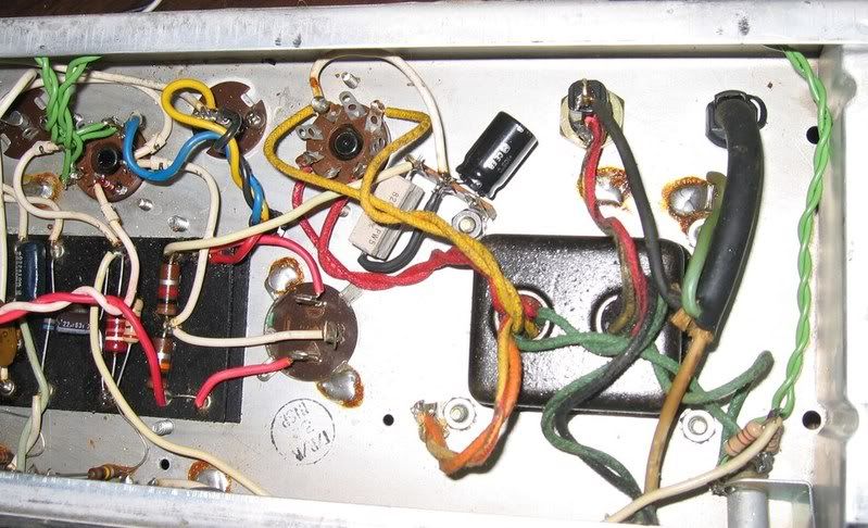
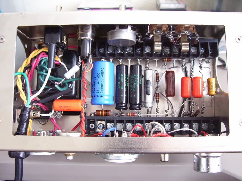
Diagram of my grounding scheme and actual layout, pics below

5F1gnds.jpg


5F1_2.jpg


5F1_5.jpg


Is the transformer bad ? really out of spec ?

Could sure use some help
 
These voltages are almost normal; the primary is probably rated 115 or 117V, running it at 122 is 6% higher, consitent with the measured voltages. Tubes have some tolerance built-in to allow 10% overvoltage.
I have a Deluxe reverb reissue (AB763) with the export power transformer; the voltages are similar to yours.
The original g2 resistors (1W) have not survived; I replaced them with 5 W. This amp is now my main recording amp, runs sometimes 24 hr continuous, never had a problem. Of course it gets hot and it is very loud...
I wouldn't worry too much, but if you have crackles, it may be a sign that something is about to give up. just check the temperature of resistors and check their value for any significant drift. Some 6v6's do not withstand elevated voltage but they generally tell you by glowing purple.
BTW, what model is a 5F1?
 
Thanks for the reply

the model - tweed champ 59-60 clone. 8" Jensen P8R Alnico

when I go to my RCA receiving tube manual it tells me that plate voltages should be 315vdc max for 6V6 (pin3)and 285 vdc max for grid 2 (pin4). I'm like 100 vdc above that on the plate and nearly as much on the grid 2. Seems higher than it nees to be for good tube life. The target output wattage is 5.5 watts output at these rated voltages.

also , I checked component values, especially resistors and they measure up fine. But I did rewire the heaters to a floating
arrangement only find it added a audible amount of buzz. So I will go back to grounding one side of the heater lead/tube pins and the other lead to the 6v6 pin 7 and 12ax7 pin 4-5 .

Also the crackling speaker distortion can be duplicated with another speaker so I'm sure its not a speaker.

Your correct about the 10K G2 resistor on 6V6, my first 1/2 watt burned. Now its a 1W and holding, but maybe a 5W is in line. More voltage more current. 10K Could be the cause of the crackle due to drift under power. Its hard to test ohms for drift under power since it can damage a DMM easily. Should the 10K G2 6v6 resistor be too hot to touch under normal conditions ? or just above room temp ?

the hum at idle increases as volume knob is increased as well. Is this normal ?

 
Yes, all the small errors added-up to really too hot for long 6V6 life. They WILL take more than the book says, and Leo Fender knew that, but 16W Pd is cooking the poor plate.

You could this, you could that, but.... just put in 6L6. Any modern 6L6 will be sweet at 380V 16W. The added heater demand may reduce voltages all over.

That does not explain the crackles. Or the hum. That is a VERY tight build for a high-gain amp (not hi-gain like a modern Metal-Masher, but still gain of 15,000 from first grid to last plate). Champs are very tightly built inside, and layout is critical.
 
PRR

OK , a 6L6 is pin compatible and my RCA guide tells me 360 vdc max at .9 amper. Add in the 12ax7 at .1 to .3
amper and that puts the current draw just over 1 amp the transformer should take that with a reserve of .7 to .8 amper no problem. I'll give that a try.
 
be careful with those out of circuit voltage tests, loose wires flappin with 750,

hopefully you measured the two halves and multiplied by two. i popped a DMM on this 670 pwr xfmr.  :mad:
 
> a 6L6 is pin compatible and my RCA guide tells me 360 vdc max

That's the 1939 spec. The oldest sheets show 400V, but the old base material deteriorated, so they changed the spec. Later they improved the base but never changed the spec, because RCA had higher-price tubes to sell.

Nearly any modern "6L6" will be made to 6L6GC specs or better. 450V rated, and they are known to live a long time at 500V. So many guitar amps run "6L6" past 450V, that I think all modern makers use the 500V metals and processing, even if they don't say so.

If someone sold a "6L6" today which died at 361V, they would have SO many unhappy customers that they would go out of business.

All that said... I think what you really want is another big cap and power resistor. 2K 10W plus say 16uFd between the first cap and where you get power to the OT and power tube. Then the 6V6 will be right at ratings and good proportion for 7K load, plus you have less supply ripple. However I see this would not be easy in this chassis.
 
Neat looking build you've got going there.  If you want to keep the 6V6 you could simply replace that 450R cathode R with something more like 680R up to 1k to reduce the standing current.  In my Silverface VibroChamps I've used about 800R to good effect.  What brand of 6V6 are you running?  One of the most durable of the newly made brands is JJs.  Big bottle for a 6V6 and sounds more like a 6L6.  It can take a really high voltage and higher plate dissipation.  Not very expensive, either.

Oh, I see you've got a bias adjust pot in there.  Not sure that's gonna work well at 30-50mA DC--yeah it's only half a watt, but a pot on the cathode might be noisy.  I would put a rotary switch in there and a set it up to switch a larger parallel R across a 1k fixed cathode resistor.  That way you can use little 1/2W parts on the switch since they won't be taking much current.  Say 10k, 5k, and 2k2 on a 3 pole switch.

On the buzz--it's hard to tell how you've wired the input jacks.  Looks like they are the correct NC switched types with the rings grounded and the two 68k plus 1M standard Fender arrangement?  Maybe recheck that wiring, because if the inputs float with nothing plugged in they are just antennas.

Good luck!
A P
 
That extra RC stage that PRR mentions does work.  I did it in one of my VCs.  PRR may have been the one who suggested it a couple of years ago.  I think I used ~1k 5W and 20uF.

VC_after.jpg


Very good info here , PRR, Analogpackrat

I'll try that RC suggestion and see what happens.

Don't know why my RCA manual has 1939 info , I need to update this.

I have some old steel 6L6's I might try out.

CJ, Yes I did measure each leg and 351 x 2 on the socket, my dmm will handle 600V max, so its easy to forget and only takes a milli-second mistake. It might be fused.
 
Was just thinking about the 6L6 and power output.

Will a 8" speaker and a 8W Output transformer handle it ?
 
I've got a P8R in one of my VCs and it is rated for 20W+, IIRC.  No problem.  Your output transformer is pretty small.  What's the max DC current it's rated for?  A 6L6 will put out about 10-12W in class A.  Personally I would stick with the 6V6 and just swap out the cathode R to keep the power dissipation down in the 12W range.
 
Its a Hammond 125C with adj. impedance and output taps. Max 8W rated. Don't know what the max DC current is

I would like to keep the 6v6 if possible. But the real solution is to lower the mains voltage or manipulate the secondary output voltage. I have tried dropping 200-300 ohm dropping resistor at pin 8 - dc output of the rectifier. and this lowered the voltages but this may not be a good approach since it will lower the current to the rest of the circuit. And it changed my bias on the 6v6 considerably to the point where I would need to chage the bias resistor value to something else. This is where PRR suggested a
RC add on, I'll have to fiddle with this.

I understand the cathode resistor your referring to is the one I have at 450 ohms 5w that goes to the Bias
pot ( 200 ohms ),  yes ?

What value do you suggest ? , I thinking a higher value between 750 - 1K ohms 3-5w want to keep bias current between 30-40ma
 
Im thinking I'll just go get me a Edcor XPWR014 PT and the voltages should be in the ballpark.

300-0-300  should give me a ~ 320-0-320 with 120vac at the mains.
 
Back
Top