G-PULTEC problems, please help!

GroupDIY Audio Forum

Help Support GroupDIY Audio Forum:

This site may earn a commission from merchant affiliate links, including eBay, Amazon, and others.

daveee

Member
Joined
Nov 24, 2008
Messages
18
Location
Liverpool, UK
just finished building my first eq, a gyraf pultec :)

i paid quite a bit of attention to detail with the construction (e.g. double-checking all wiring and component values)... but sadly it doesn't work as intended on first test, and i'm wondering if anyone could suggest where i should begin in terms of fault finding...

basically the controls work pretty much as expected, although with all pots at 0 (and even in bypass mode) there is a lack of bottom end (as if it's rolled off). the signal is also a little distorted. when i turn up the low boost pot the bottom end is boosted but the signal becomes more distorted (with low boost at around 2 or 3 the bottom end is roughly where it should be when bypassed, if you see what i mean).

a slightly odd thing i've found is the +250V HT rail is actually at around 275V (i guess because the first power trafo is outputting a slightly high 15V) but i assumed this would be within the tolerated range... maybe a mistake?

any ideas? (thanks in advance!)
 
Did you use an input xfrm or just the output?  I'm not sure whether bypass bypasses the transformers or not, but sounds like it may be one legged output.  Double check all the polarities on your xlr's and make sure you have the transformers hooked up right. 
 
thanks for the quick replies!

- yes i'm using LL5402 for input and output transformers, they're mounted on the PCB so can't be hooked up wrong i think...
- all polarities are correct (to/from XLRs, and between amp and filter boards).

i think i'm going to try running a low freq sine wave through it and tracing with the scope and see what i can find...

if there's any more suggestions i'm all ears :)
 
ok this is really strange...

i've just realised that the unit works perfectly when first switched on... then after a few minutes this happens: (i'm really not an expert on circuit design so you'll have to forgive me if this is obvious!)
- +6.3V heater voltage slowly decreases to around 2.5V
- +250V HT slowly increases to around +275V
- sound becomes quieter, distorted, with less bottom end.
- if i switch the unit off and on, it works ok again.

i didn't realise this initially because i was waiting for the tube to warm up before running audio through it.

anyone know what this could be?
 
daveee said:
- +6.3V heater voltage slowly decreases to around 2.5V

That's a big problem, your psu doesn't work...
Bad power transformer?
Maybe too small?
 
This is most probably because of too little cooling on the heater regulator - it gets too hot and powers down. Try a (much) bigger heat sink.

Lets make this the one and only
[size=36pt]"Official" GPultec help thread
...[/size]

Attached a .JPG image with a simplified explanation of the filter workings - if you need to figure out what parts do what job:

In rough outlines: The pultec filter can be thought of as a simple 10:1 or 20dB attenuator - the 10K ohm of the "boost high" potentiometer and then the 1K ohm of the "cut high" to ground. This is also the bypass condition. So this 10K/1K forms the basis of all our filtering, and we put in approximately that amount of makeup gain after it, to level things out.

All the filter functions can be thought of as various sorts of partial bypassing of this attenuator:

The high boost, e.g. simply bypasses the 10K resistor with a frequency-selective short. Depending on how you set high-boost pot, you partially short out part of the 10K in the 10K/1K divider, thereby NOT attenuating as much in that frequency area (which comes out as boost after the linear makeup gain stage). Frequency select is just a LC filter that has low impedance at resonance freq*, shorting specific frequency bands more than others across the 10K part of the divider. The Q pot simply adds a series resistance to the LC filter, thereby reducing resonance steepness.

The high cut is very much the same, if you look closer: the 1K part of the 10K/1K divider is being partially shorted by a capacitor to ground, meaning that higher-than-cutoff-frequencies signal is attenuated EVEN MORE than the 20dB (because it reduces the 1K impedance above the capacitor's take-over frequency). Frequency simply depends on capacitor value*.

On a side note, you can see that we can present a VERY low load impedance to the input transformer if we boost highs AND cut highs at the same time. This why input transformer must be relatively low-impedance and low-resistance: otherwise it will limit amount of boost available by introducing a virtual resistance in series with the 10K. This is why I suggest e.g. the LL5402 as input transformer.

The low boost is slightly different, as it is a circuit that is put in series with the 1K part of the attenuator, meddling with (enlarging) its apparent resistance at low frequencies. Think of low boost as a filter that sits between the ground end of the 10K/1K attenuator and the actual ground. When "boost low" control is at minimum function, the  potentiometer is simply shorted, and the filter is exactly like we described above. But this short to ground (below the 1K part of the 10K/1K attenuator) can be gradually replaced with a capacitor in stead. What this does is to gradually introduce a higher impedance to low frequencies, making the 1K part of the attenuator in effect seem to be HIGHER resistance at lower frequencies, thus attenuating LESS against the 10K (and less attenuation, again, equals boosting when seen after the makeup amplifier)

Last - the low cut - is different from all the above, as it does not mess with our 10K/1K divider: In stead it takes the output signal from our previous divider and forms a high-pass filter consisting of a low-cut capacitor against the 10K resistor (or against the interstage transformer ~10K impedance). In order to have non-permanent but variable low cut, we simply short said capacitor with a 100K potentiometer: when potentiometer is at full resistance 100K, the capacitor dominates and attenuates below its corner frequency, but as potentiometer resistance is reduced towards zero, the capacitor is gradually shorted and taken out of the equation until when all the way down the capacitor shorted, there is no longer any attenuation or filter..

..All this just a quick description, but should be informative enough to let most of the supposed magic out of that circuit.. :)

Jakob E.
 

Attachments

  • G-Pultec - Filter Explanation.JPG
    G-Pultec - Filter Explanation.JPG
    772.6 KB
Jakob is right (of course)mine did a very similar thing regulator was shutting down bigger sink and it's all better
Good luck
 
thanks jakob, i was hoping you'd see this thread :)

i'm using a fairly standard TO220 heatsink, a C-shaped one about the size indicated on the PCB silkscreen, with thermal paste... but it does seem to be giving off a rather large amount of heat... i'll try and find a bigger one and see if that helps...
 
yes!! that's fixed it.

so for future reference...
i used this heatsink to start with:

to220-bolt-on-heat-sink-rc.jpg


and replaced it with one like this:

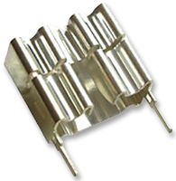
4465963.jpg

(although black and without those pins)

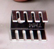
do you think i could be even better off with using one with more fins? like this:

HSink220TN.jpg


don't have any to hand so would have to order.

had it running for about 30 mins now with no problems so it seems like the other one will suffice.

thanks everyone!
 
gyraf said:
Lets make this the one and only "Official" GPultec help thread...

I agree, there's been a lot of threads about G-Pultecs recently, although they has never been a "official" thread. I myself have a few questions about my G-Pultec but have been holding off because I didn't want to create more threads.

This is a excellent idea...

Thanks

J
 
I'm cool with an "official" thread finally.

Any idea how to change around the gain. I have one unit that is -3dB and another that is -4dB, how can I at least make them the same?
 
daveee said:
yes!! that's fixed it.

so for future reference...
i used this heatsink to start with:

to220-bolt-on-heat-sink-rc.jpg


and replaced it with one like this:

4465963.jpg

(although black and without those pins)

I used a chunky black one like that and ran it for almost 18 hrs straight no problem. Glad that was an easy fix!

do you think i could be even better off with using one with more fins? like this:

HSink220TN.jpg


don't have any to hand so would have to order.

had it running for about 30 mins now with no problems so it seems like the other one will suffice.

thanks everyone!

I used a chunky black one like that and ran it for almost 18 hrs straight no problem. Glad that was an easy fix!
 
benlindell said:
I'm cool with an "official" thread finally.

Any idea how to change around the gain. I have one unit that is -3dB and another that is -4dB, how can I at least make them the same?

Try some other/more tubes - stage gain depends on exact tube data. Filter loss varies with the actual end-to-end resistance of your 10K Hi-boost potentiometer (and pots are often +/-20%)

Jakob E.
 
Can anyone let me know what they used for the inductors, and offer sonic opinions?
20mH, 47mH, 100mH, 100mH

I am also wondering what these values should be for the G-Pultec

(I am not yet well-informed in inductors technology, still learning)

Max DC Resistance:
DC Current Rating:
 
daveee said:
just finished building my first eq, a gyraf pultec :)
Hi, I was wondering if you would let me know where you sourced your inductors and the part numbers if possible. thank you kindly

Can anyone help me with this?
 
Is there anyway to add a trimmer and tweak the levels? prehaps the 470K before the gainstage?
 

Latest posts

Back
Top