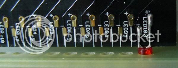
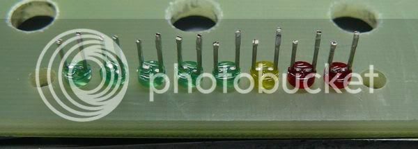
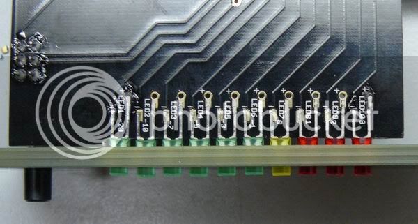
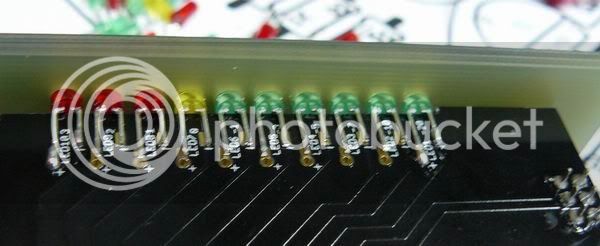
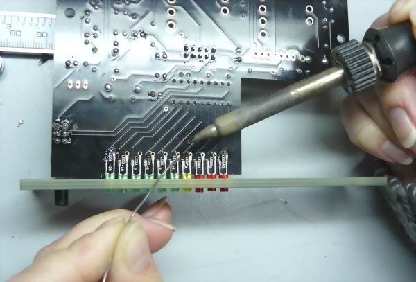
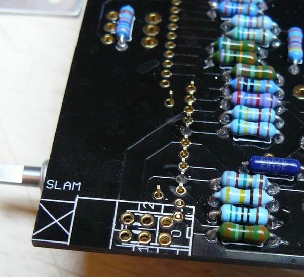
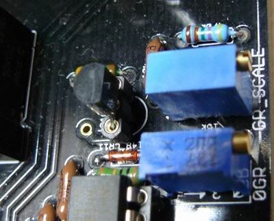
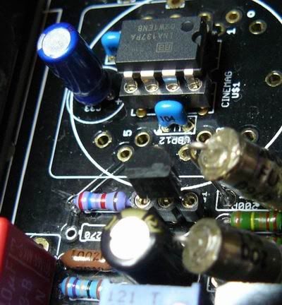
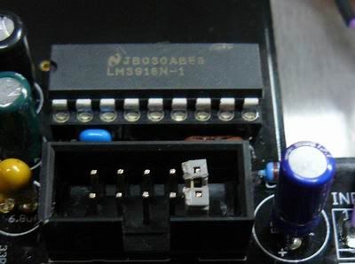
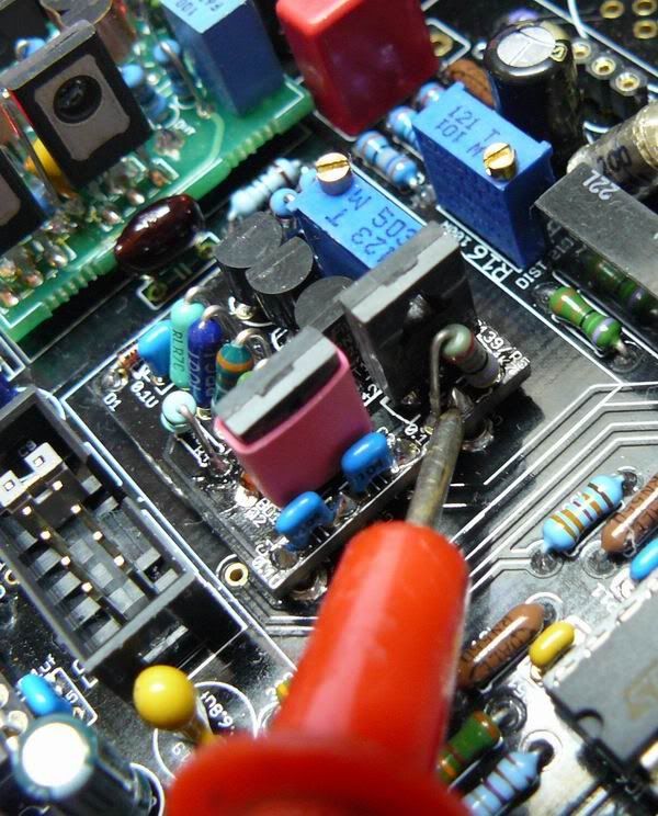
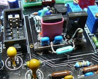
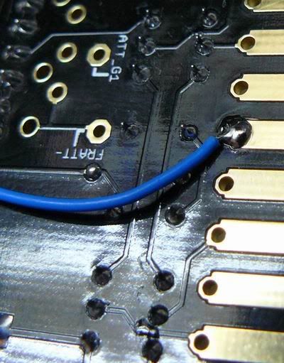
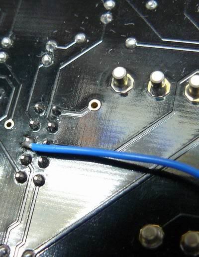
Hi guys, we carefully checked all kits and almost ready to send them.....
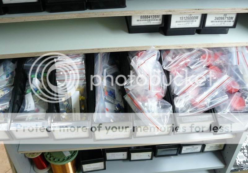
BTW, maybe, there will be some kits available again
Meanwhile, please take a look at the documentation here:
http://twin-x.com/groupdiy/thumbnails.php?album=417
Update: last version docs, everything is here:
http://ij-audio.com/downloads/51XF76.zip
Download the files, take 10 min to meditate on all this, than,
after you catch the logic, take some time to read schems.
As an educational reading, schematic redrawn in the way it is easy to understand how 1176 works.
I tried to make this unit 1176'is much as possible, however, if I have a choice, will never use "original" 1176 amplifiers of any version.
Yes, OK, this kind of compression did many great music, and this sound wrote history.
Anyway, kill me, the 1176 amps are out of my taste after building of some clones, comparing with "original", etc....
I had to make it more versatile, and to have more options with sound color.
You have some really nice surprises here. This unit can run at +/-16V, as well as on both +/-16 and +/-24 rails of 51X,
try my cascode topology input stage amp, with API output amp and Ed Anderson's 11148 replica for 500 format,
and tell about sound; yep, lot of color, all you freaks will like it

 ;D ;D ;D ;D ;D ;D ;D ;D
My taste is my input amp, LL1524 and my own out amplifiers (with all DOA's are running on +/-24V), it is less colored,
but the color itself is way more "pedigree", well, leave my fubaru English, back to stuff!

The next 2 posts will be reserved for assembly guide, FAQ, some howtos, and test procedure.

BTW, maybe, there will be some kits available again
Meanwhile, please take a look at the documentation here:
http://twin-x.com/groupdiy/thumbnails.php?album=417
Update: last version docs, everything is here:
http://ij-audio.com/downloads/51XF76.zip
Download the files, take 10 min to meditate on all this, than,
after you catch the logic, take some time to read schems.
As an educational reading, schematic redrawn in the way it is easy to understand how 1176 works.
I tried to make this unit 1176'is much as possible, however, if I have a choice, will never use "original" 1176 amplifiers of any version.
Yes, OK, this kind of compression did many great music, and this sound wrote history.
Anyway, kill me, the 1176 amps are out of my taste after building of some clones, comparing with "original", etc....
I had to make it more versatile, and to have more options with sound color.
You have some really nice surprises here. This unit can run at +/-16V, as well as on both +/-16 and +/-24 rails of 51X,
try my cascode topology input stage amp, with API output amp and Ed Anderson's 11148 replica for 500 format,
and tell about sound; yep, lot of color, all you freaks will like it
My taste is my input amp, LL1524 and my own out amplifiers (with all DOA's are running on +/-24V), it is less colored,
but the color itself is way more "pedigree", well, leave my fubaru English, back to stuff!
The next 2 posts will be reserved for assembly guide, FAQ, some howtos, and test procedure.


