Mulletchuck:
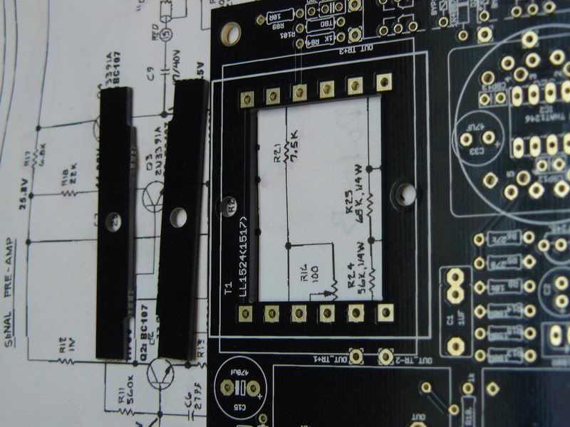
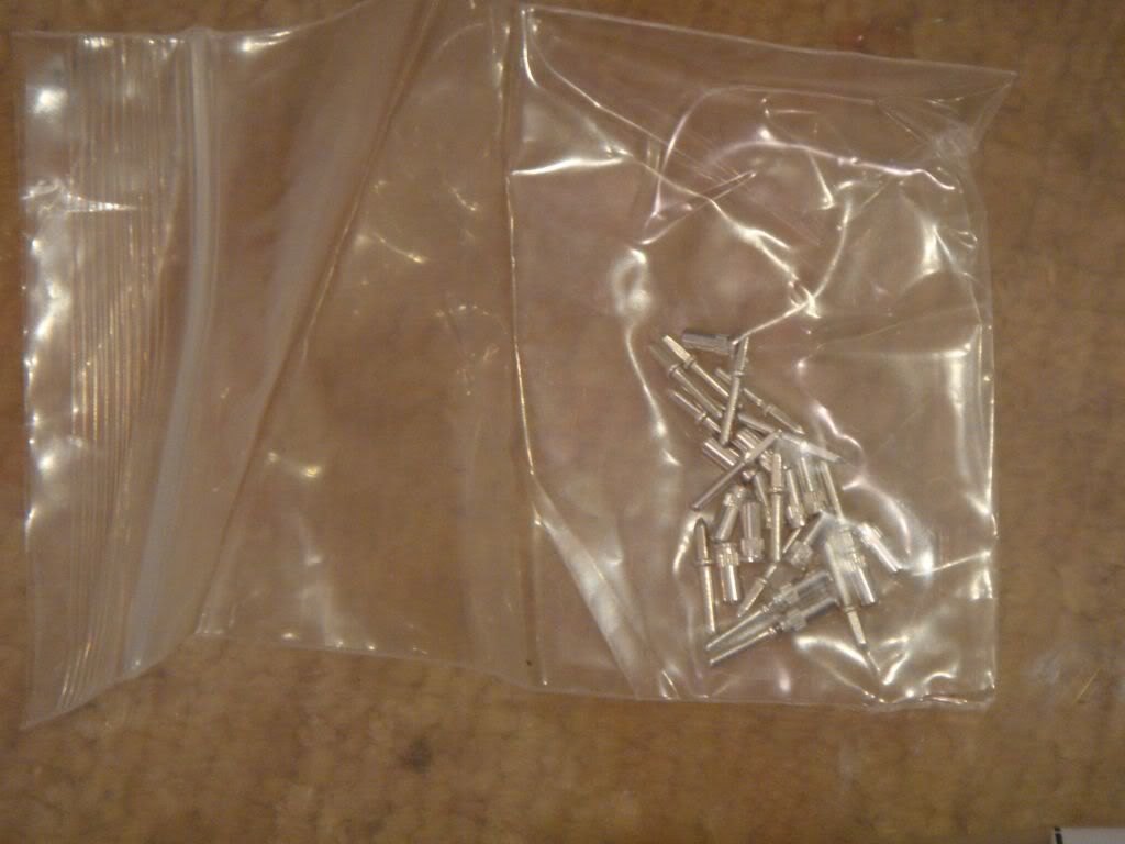
Thank you for the tip on the spacers, I would have thought they were junk too.
I have not started the build, because I have not collected all the parts yet. I still need the input transformer, I have been mailing back and forth with the fellow at Cinemag, to see what they have that would work. I will post the part number they give me when I find out.
If anyone knows what cinemag fits, please post the part number, rather than having me torture the folks over at Cinemag as we reverse engineer the pinouts.
I am glad someone else is building this too, because maybe we can help each other and leave some breadcrumbs. I will take pictures as I assemble mine, and try to post some sort of information on it.
Regarding Attenuators
I am also confused on this, there is no data at all in the materials that I could find. There is one comment earlier in this thread that refers to needing to modify a bracket, I think this might be because maybe the attenuator replaces the input pot and the hole is the wrong size, or the nut is too thick. If you look at the schematic it appears that this pot is the output of the THAT 1246. But I haven't got a clue as to what the little x's signify on the schematic (I did decode a guess that FRATT means from attenuator, and TOATT means to attenuator and att_61 and att_62 must be the attenuator, but what the attenuator circuit is is sort of greek because I don't know what kind of attenuator would have 2 connections to ground (dual T's)... and I wouldn't think that a balanced attenuator would be grounded at all.... maybe this is some sort of code that I (very new to this) have never seen on a schematic. I am GUESSING that somehow the notion is to put an attenuator before the transformer, install it with wires, in the same hole that the input pot goes in (when I say Pot I mean whatever came with the kit for that input hole on the front panel, I don't know if it is a pot or a grayhill) although the line is balanced so I would think the attenuator circuit would be an H or a U, neither of which are grounded.
That's a guess.... Yep)
Regarding Ratio Card
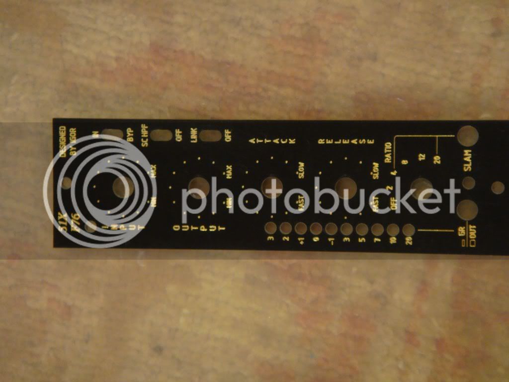
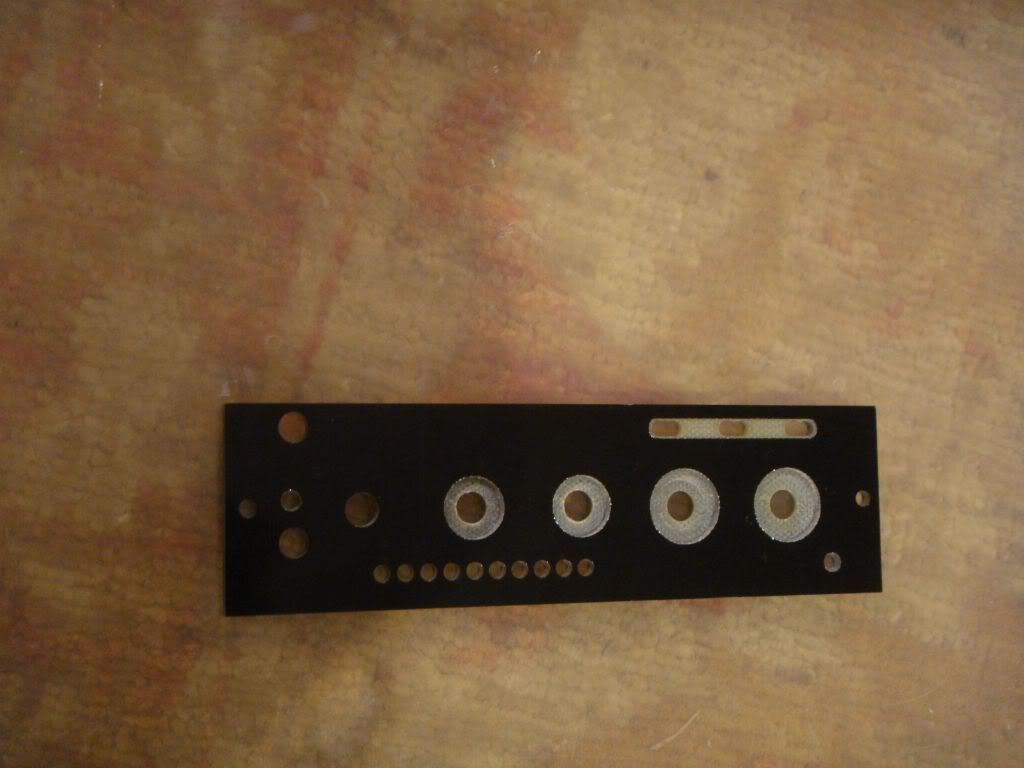
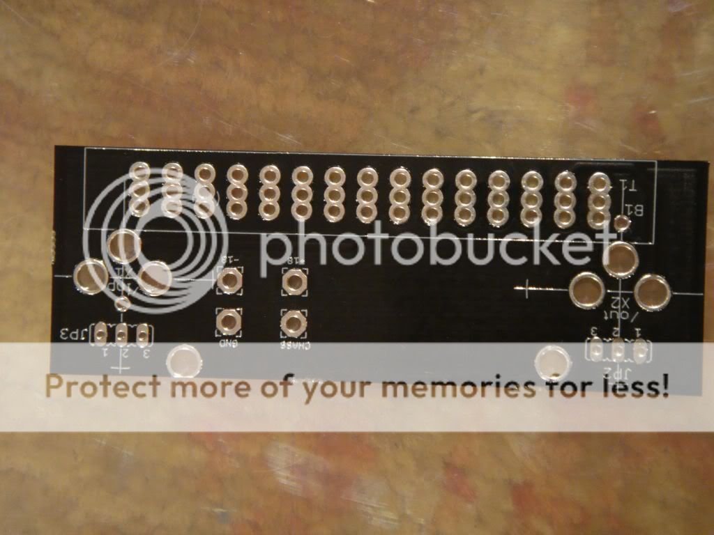
Not lining up with holes on front panels, apparently there is some notion that this kit can be built not as a 500 module but in a rack. At least that is what is apparent from Igor's concise reply to this post
http://www.groupdiy.com/index.php?topic=43338.msg565065#msg565065
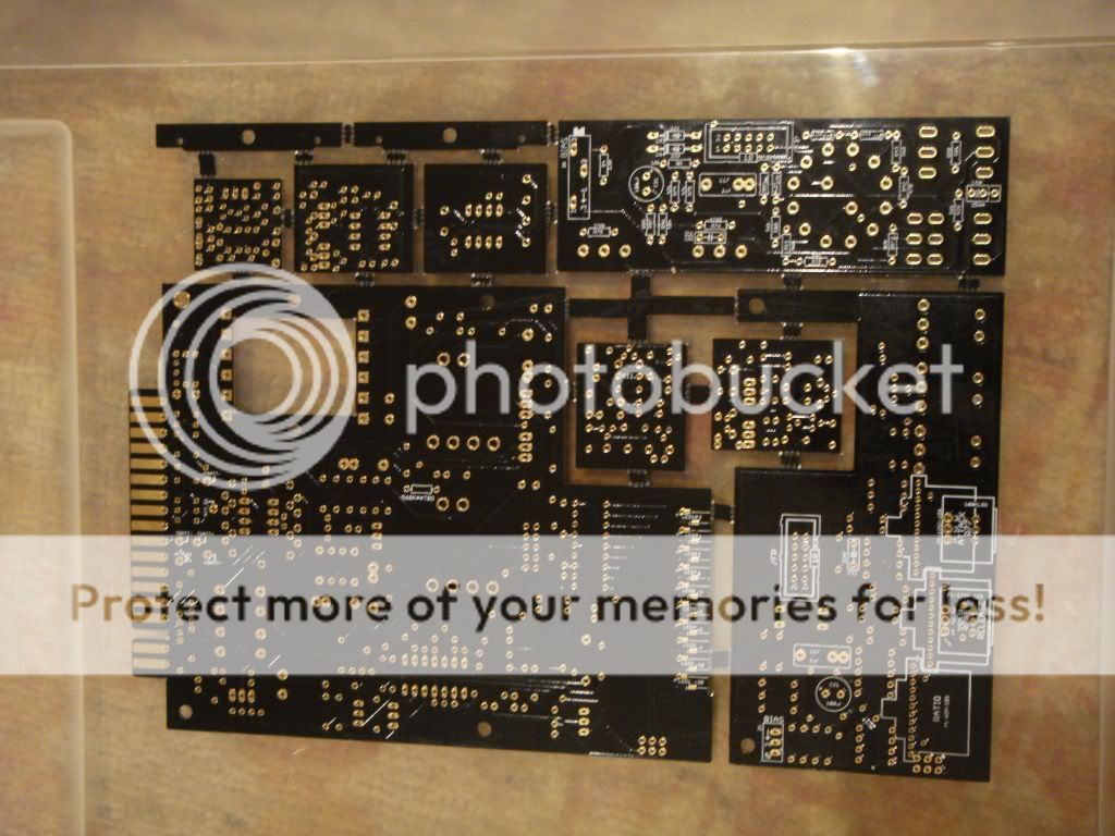
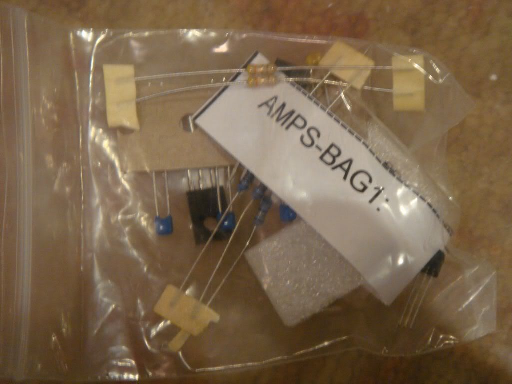
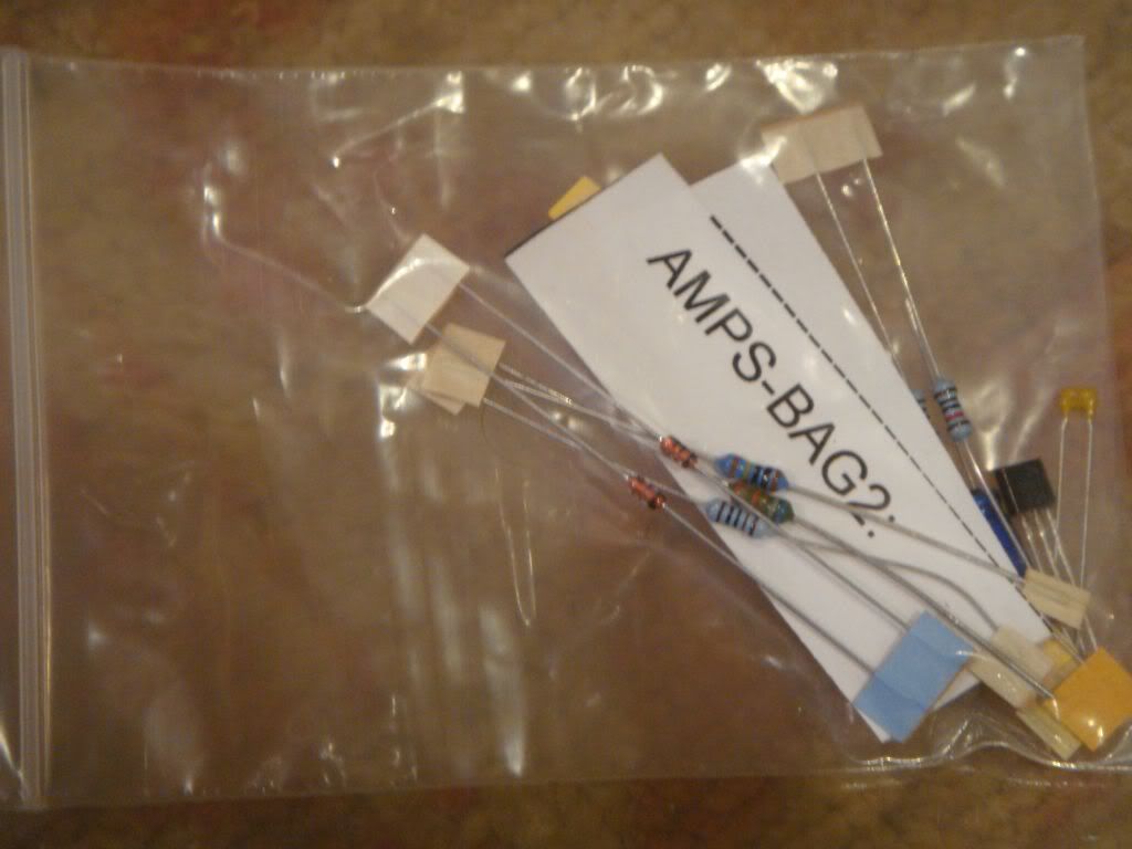
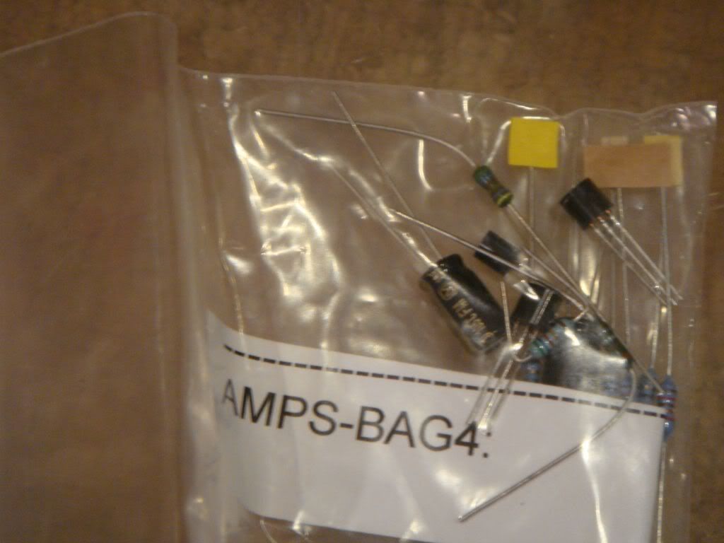
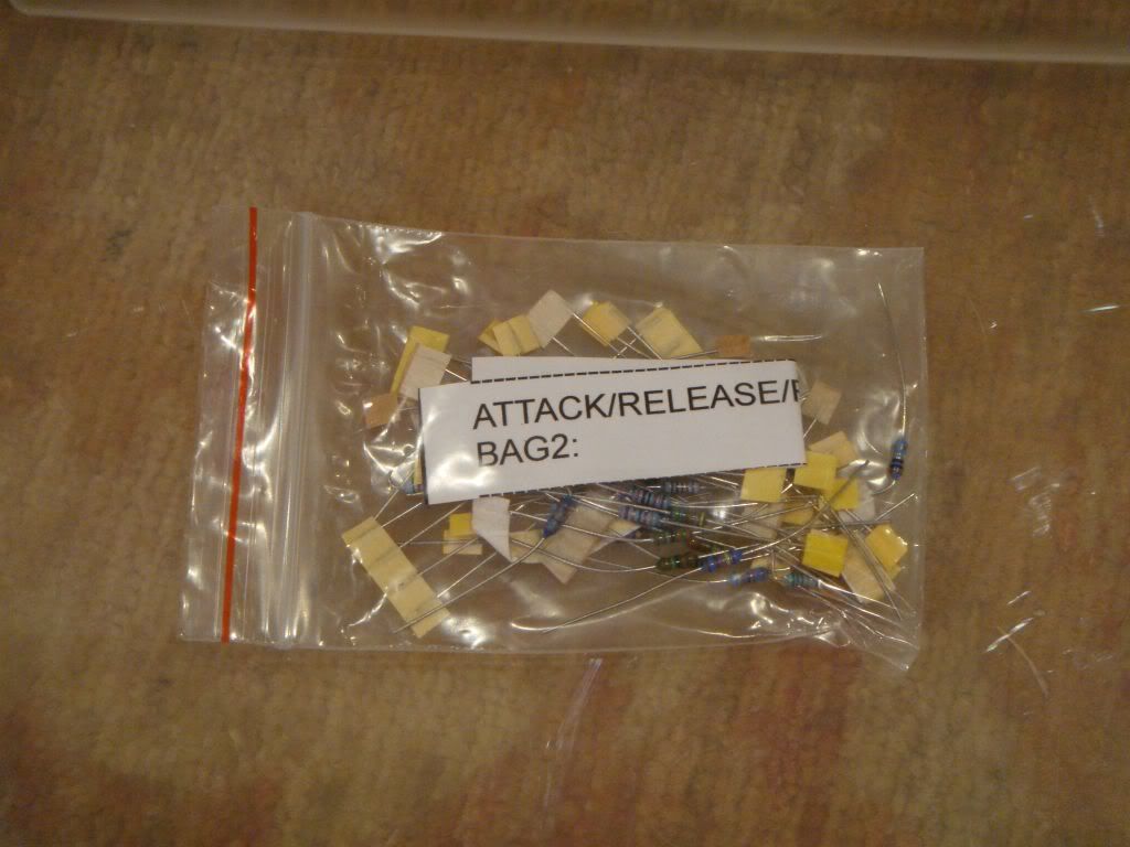
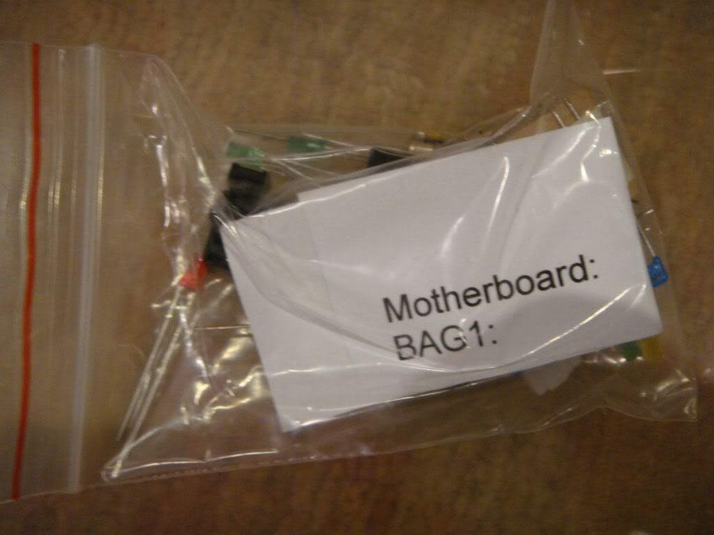
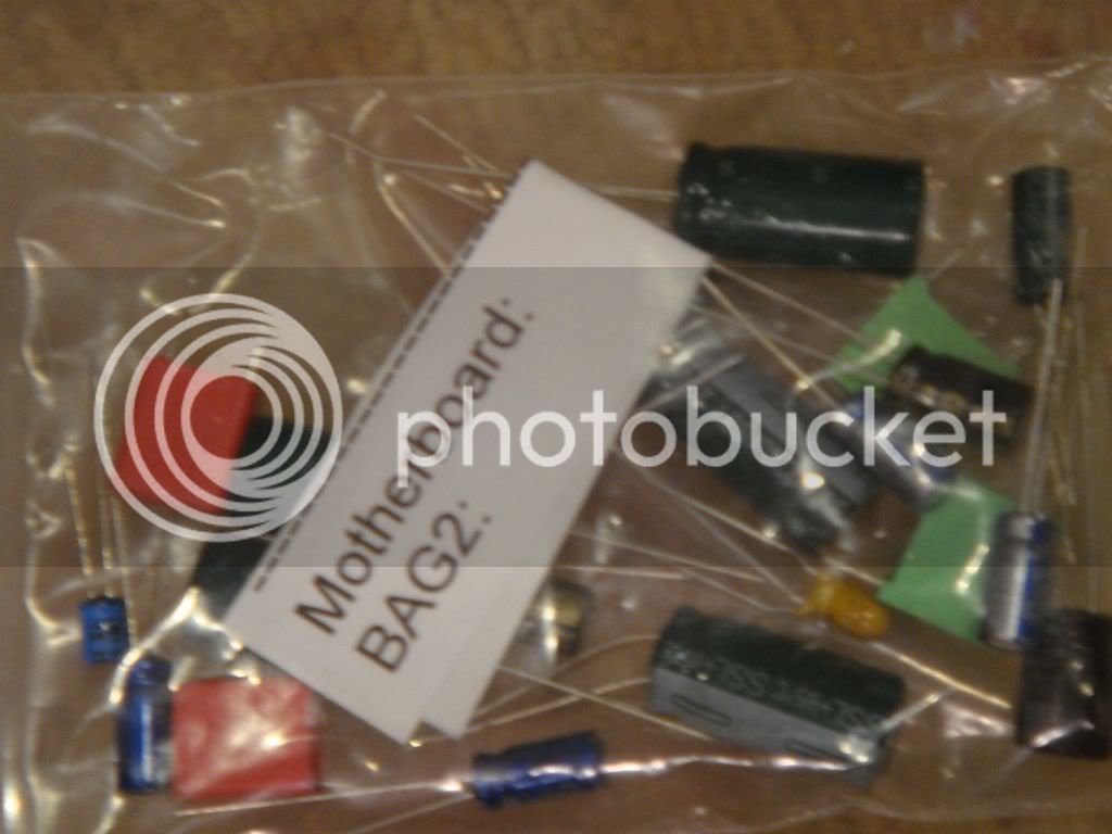
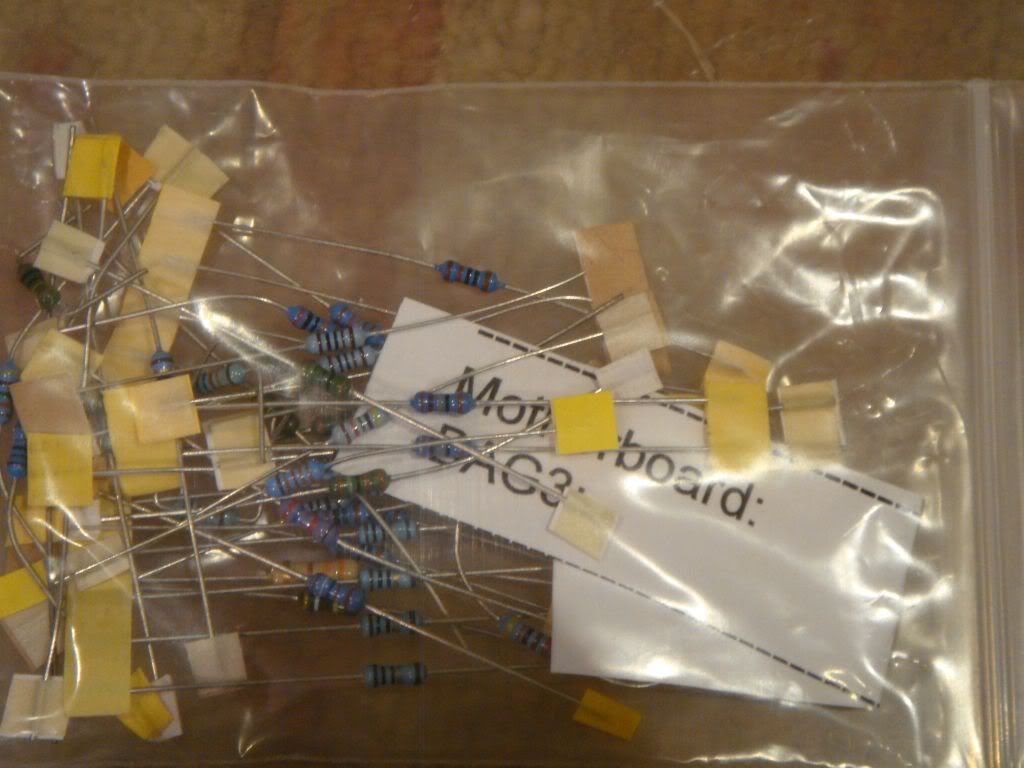
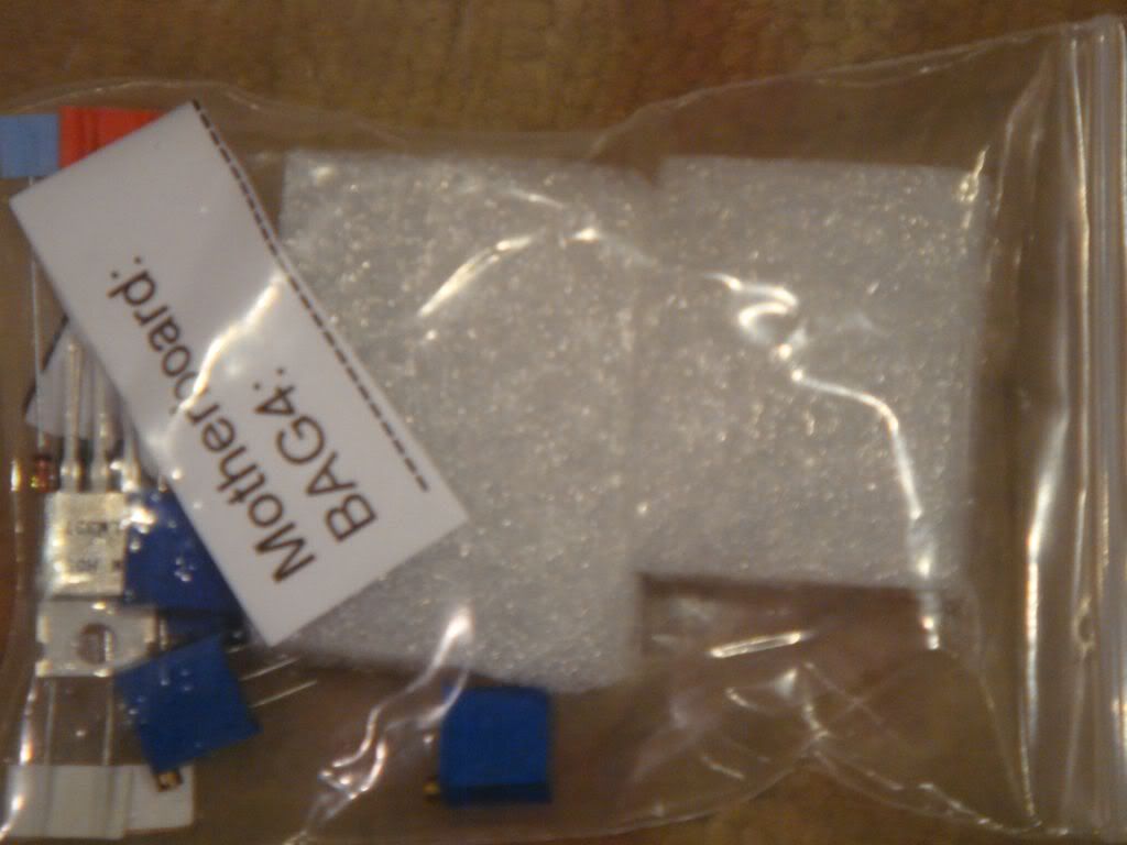
This is further confirmed by the fact that the card comes with a 1U_top card that sort of duplicates the function of the other card. It also comes with a little card that has 2 xlr connectors and a 15pin card edge connector (like a 1 unit API rack. I assume this is so you can wire up the card in a 1 U rack. I will post a list of pictures of what comes in the kit, and update the info as I get through the build.
Thanks for your post, it motivated me to begin doing an inventory of the kit.
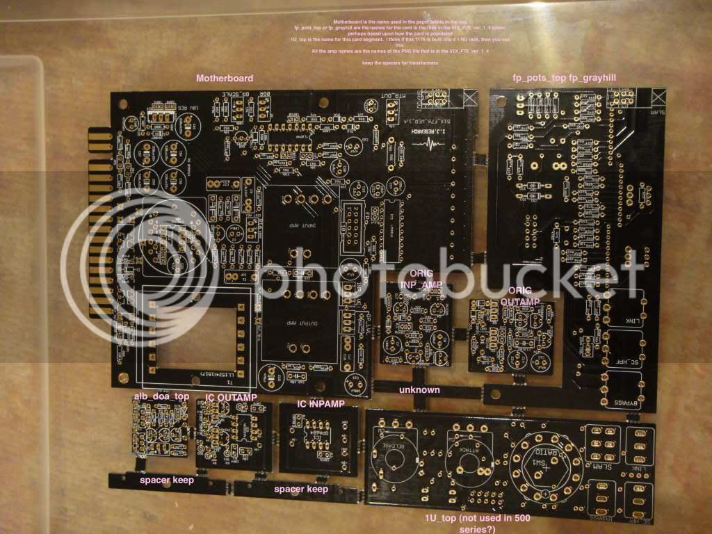
My next post is a picture of picture of the segmented card as it arrives in the kit, labeled as I currently understand it.


