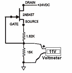
Anyone with a FET matching device willing to help a chap?

GroupDIY Audio Forum

Help Support GroupDIY Audio Forum:

This site may earn a commission from merchant affiliate links, including eBay, Amazon, and others.
T

tubejay

Guest
I've been trying to find a cheap variable power supply on ebay to build PRR's FET matching device, but I GIVE UP! I can't find one cheap enough. Is anyone out there who's built one of these devices willing to match my fets for my G1176 for me? I'll cover all shipping costs etc...

Pretty pretty pretty please???

I want to get moving on this beast.

Thanks!!!!!!!!

Jay :green:
 
> cheap variable power supply on ebay to build PRR's FET matching device

I don't remember that gizmo, but I bet you can use a 9V battery and a 1K pot?
 
PRRFET-sort.gif
[/url]

It's really a great gizmo.

:thumb: :sam:
 
Thank you Seth, and thank you PRR for the design!!

:guinness: :guinness: :guinness: :guinness:
 
check this
http://www.geofex.com/Article_Folders/fetmatch/fetmatch.htm

That's a nice one as well and about as easy. If you happen to use a DeLuxe opamp be sure to decouple & tame it enough, as I faced after the first strange results. After that it was fine and using this overspecced OP07 (with offset smaller than Michael Jackons nose) felt good :wink:
 
What about this matching method:
(asuming a N-channel JFET)

Connect Drain to + of 9V battery.
Connect Gate to - of 9V battery.
Connect DVM between Source and - of 9V battery.
What you measure on the DVM should be very close to
the threshold voltage.

I've done this with a 100k resistor in parallel to
the DVM, worked fine for finding matched (low offset)
pairs.

But thinking it over again, for finding the
threshold voltage it should even be
better without that resistor, just using the internal
resitance of your DVM.
That means you could select FETs just with a battery
and a DVM, without any further circuitry.

For matched pairs, working at a certain bias current,
it might be better to select them at approximately that
current, i.e. add a resistor to the DVM and battery
for your equipment. (;->)

JH.
 
The referenced FET sorter is for matching at a specific value of bias resistor, for use in a linear amplifier.

For variable-resistance FET use, this won't do. FETs can read the same at that one test condition and be wildly different at other conditions.

FETs vary a lot, but within one type, two measurements are all you need to interpolate the properties at all conditions.

PRRFET-sort2.gif


Read the voltage with just the 100K resistor. This is (as JH says) roughly the threshold voltage, the gate-source voltage to make zero (super-low) current flow. Probably 0.5V to 8V.

Push the pushbutton to put the 10Ω resistor in. This is roughly Idss, the maximum current with gate shorted to source. About 1 to 30mA (about 10mV to 300mV in the 10Ω resistor).

So you have the two ends of the FET: current at zero bias voltage, and voltage at zero current.

Or in an FET variable resistor: you know the gate voltage where limiting will start, and the minimum resistance (maximum limiting).

We can compute the voltage and current for any inbetween condition with simple formulas. BUT if we just want a match, we can match these two points and know that all the inbetween points will track.

I suggest you start by quickly testing a lot of FETs with just the 100K (threshold voltage) test. They will be ALL over the place, 0.5V to 8V. With luck, you will find a lot all in the same ballpark. Take that lot and sort by Idss.
 
[quote author="PRR"]The referenced FET sorter is for matching at a specific value of bias resistor, for use in a linear amplifier.

For variable-resistance FET use, this won't do. FETs can read the same at that one test condition and be wildly different at other conditions.

FETs vary a lot, but within one type, two measurements are all you need to interpolate the properties at all conditions.

PRRFET-sort2.gif


Read the voltage with just the 100K resistor. This is (as JH says) roughly the threshold voltage, the gate-source voltage to make zero (super-low) current flow. Probably 0.5V to 8V.

Push the pushbutton to put the 10Ω resistor in. This is roughly Idss, the maximum current with gate shorted to source. About 1 to 30mA (about 10mV to 300mV in the 10Ω resistor).

So you have the two ends of the FET: current at zero bias voltage, and voltage at zero current.

Or in an FET variable resistor: you know the gate voltage where limiting will start, and the minimum resistance (maximum limiting).

We can compute the voltage and current for any inbetween condition with simple formulas. BUT if we just want a match, we can match these two points and know that all the inbetween points will track.

I suggest you start by quickly testing a lot of FETs with just the 100K (threshold voltage) test. They will be ALL over the place, 0.5V to 8V. With luck, you will find a lot all in the same ballpark. Take that lot and sort by Idss.[/quote]

Oh yes, that's clever - also measuring Idss with only closing one switch and adding a shunt for current measurment.

Which brings me back to the lowest part-count solution:
The 100k is not really needed for threshold voltage, as the internal
resitance of the voltmeter lets an ever so tiny current pass.
Now keep the very same connection (just the meter wired ito the
source), and switch it from voltage to current measurement.
So you'd even get both, threshold voltage and Idss, without
any extra components - just your DMM and a battery.

There's a catch, though: Most DMMs I've seen don't allow direct
switching from voltage to current measurement; they normally use separate input jacks for current. So your solution with switch will also be the most comfortable one in the end.

JH.
 
> The 100k is not really needed for threshold voltage, as the internal
resistance of the voltmeter lets an ever so tiny current pass.


Yeah, except a very few FETs may have low threshold and high surface leakage. Maybe with modern processing, that doesn't happen. But if it does, the leakage would cause a false high reading of threshold voltage, which will baffle you when none of the inbetween conditions match a "same voltage" not-leaky FET.

An even more elegant method: set up your resistor and FET attenuator, same values as you will really use. Feed the Gate with a pot across a 9V battery. Feed 10mV audio. Trim the pot for 7mV (-3dB) output. Record teh gate voltage. Feed 100mV audio and trim the pot for 10mV (-20dB) output. Record the voltage. Repeat, repeat, repeat with more FETs. Mark each FET with the two numbers, and sort until you find the closest pair.

To some degree: if two FETs have the same Idss but different Vth, you may be able to trim the drive circuit. But that has problems and is a last resort. Even so, it is fairly common to have separate trimmers to set the idle bias in each channel.
 
Look at the NS PDFs on LM317s Simple math only thing that might not be shown is a load to pull a few Ma. Three term reg often have the output voltage move up without a load.
 
[quote author="PRR"]
An even more elegant method: set up your resistor and FET attenuator, same values as you will really use. Feed the Gate with a pot across a 9V battery. Feed 10mV audio. Trim the pot for 7mV (-3dB) output. Record teh gate voltage. Feed 100mV audio and trim the pot for 10mV (-20dB) output. Record the voltage. Repeat, repeat, repeat with more FETs. Mark each FET with the two numbers, and sort until you find the closest pair.
[/quote]

Yes. When I build my stereo UA1176 clone, I did the verification of the previous selection just like this, in the real circuit. Makes sense to just use it as the method for selection in the first place. But I was surprised how well they matched, just by selecting for threshold voltage (_with_ the 100k resistor, however). Not the slightest shift of the stereo image as the gain is changed.

What always made me curious is how well the "vintage" method of linking two mono devices to a stereo pair actually works. AFAIK there's a just a box with a variable floating voltage source (battery and potentiometer) which will compensate for a difference in threshold voltage of the two FETs. How can this - just adding a fixed voltage! - work over the whole range of dynamic reduction, without shifting the stereo image?

JH.
 
Hi all. Forgive me for re-opening an old topic.

I built a little test jig based on PRR's schematic and it seems to work very well.

My question is -- how close do the voltage measurements need to be for "matching" two FETs?

Thanks!
 
JohnRoberts said:
Until you don't have any more parts to grade.

use the bast match from what you have.

JR

Good point. I was just trying to decide if I should order more FETs to get closer matching pairs.

I started with a batch of 15 pieces and arranged them by threshold voltage. Most I can pair off within a tenth of a volt, but it seems like I don't really have enough FETs to be picky about the Idss measurement.

Would you recommend a larger batch, or is this good enough for the typical FET compressor application?

Thanks!

 
15 is plenty. You should easily find at least two perfect matches, but in all likelyhood more than that.

If you want to get this matching thing absolutely perfected, here's a guide to plot curves. http://www.axtsystems.com/index.php?option=com_content&view=article&id=46:1176lnfets&catid=34:1176ln&Itemid=62

You will be able to make perfectly tracking stereo units this way (linked compression), with no external calibration etc. mixing devices some people are even selling on this forum.
 
The last and only time I matched parts (for an old phono preamp kit)  I started with a few hundred parts, I basically put them in paper envelopes with the Vgs written on the envelope. After I was finished I paired them up.  I still have some  laying around. Even with a pool of hundreds I did not get perfect matches, but decent.

JR
 

Latest posts

Back
Top