JENSAMP-51X (Germanium Mic-Pre by Darius Kubarth)

GroupDIY Audio Forum

Help Support GroupDIY Audio Forum:

This site may earn a commission from merchant affiliate links, including eBay, Amazon, and others.

[silent:arts]

Well-known member
Joined
Jun 4, 2004
Messages
5,235
Location
Berlin, Germany
rev04 documents:

Jensamp-51X rev04 schematic
Jensamp-51X rev04 gain switch
Jensamp-51X rev04 PCB overlay
Jensamp-51X rev04 Parts-List

_______________________________________________________________________________________
now, with the 5th birthday of the Jensamp we are ready to release the 51X version ;D

Jensamp51x.JPG


some history about this project:
http://audio.kubarth.com/jensamp/

the designers coming out (and how long it took to become 51X):
http://www.groupdiy.com/index.php?topic=28546.0

and last but not least (but in german) - the dialog (sometimes monologue) between the father of the circuit and the mother of the 51X PCB ;D:
http://www.nrgrecording.de/nrg/viewtopic.php?t=1930

however, I won't describe this project further, please read the links.

So far we have:

Jensamp-51X rev02 schematic
Jensamp-51X rev03 schematic
Jensamp-51X gain switch schematic
Jensamp-51X rev03 Parts-List

Jensamp-51X rev02 PCB overlay
Jensamp-51X rev03 PCB overlay

+24 / +48V Mod note: this is not GDIY511 compatible anymore

R6 is either a 470R resistor, or better a 1k multiturn trimmer.
how to set the trimmer kubi describes in his Einmessvorschrift (still needs to be translated)

NOTE: if you don't like the loud pops while switching the gain switch (and why would you like it?) change the polarity of the electrolytic C7. this affects all revisions below rev04.

distorting HiZ Input-fix
 
Lundahl 1538/1517 versus Haufe ST8456/RK240:

JENSAMP51X-Lundahl-Haufe.png


note: both Jensamp-51X are build without any component-matching, and used transformers.
Generator out = 150/200Ω
Analyzer in = 600Ω
Everything measured with Neutrik A2, except the input impedance which was an AP portable one.
 
whats the rev2 fix all about??
I remember you said something about a pad and polarity something??
looks great.
 
3nity said:
whats the rev2 fix all about??
I remember you said something about a pad and polarity something??
looks great.

documentation will come for this.

here you can see the problem:
rev02polbug.png


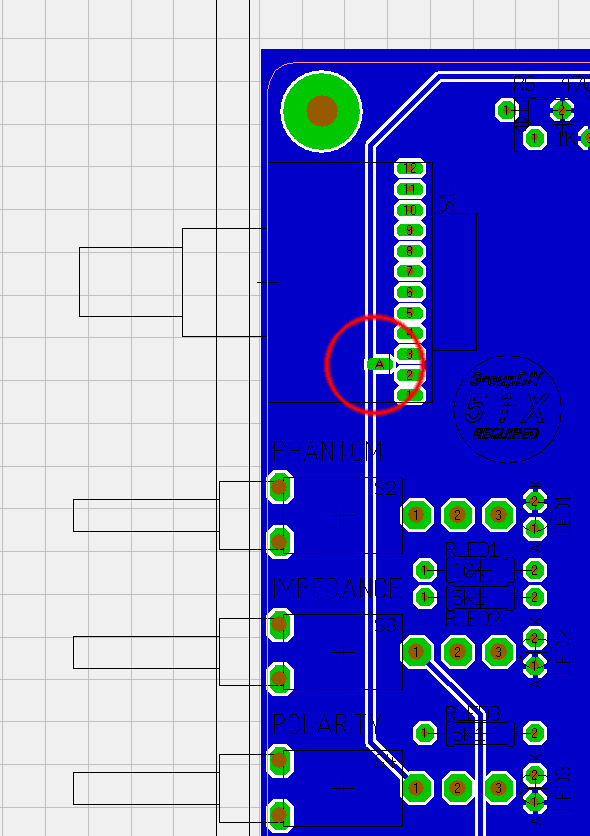
rev02 PCBs ship with cut PCB trace (we don't want -24V at the gain switch).
the wire to recreate the polarity function you have to do on your own.

however, there will be some documentation for this soon.
 
transformers are only for pikatron i think!
But you can adapt if you can!

Volker is there a mistake with the board polarity circuit..is it easy to repair?
As i see it on rev2 schematics it looks like audio its already switched on relay.
Sorry for the bombing over here!
 
Guys, give me some time ...

Transformers:
Input = either Lundahl LL1538 or Haufe ST8456
Output = either Lundahl LL1517 or Haufe RK240/2M aka Telefunken 6L.5062.003.01-A001
no Pikatron involved

3nity said:
Volker is there a mistake with the board polarity circuit..is it easy to repair?
As i see it on rev2 schematics it looks like audio its already switched on relay.
Sorry for the bombing over here!
the position of the impedance switch and the polarity switch is reversed between rev02 and rev03.
both are working perfectly. rev02 just doesn't fit the front panel silkscreen - but since you are doing your own frontpanel: no problem.
with one further PCB trace cut and a 2nd wire the switch position can be done like in rev03.
but for those scenarios you have to wait for the documentation, which I will do.

But for now I have to renovate my daughters room first, she will come back on saturday!
 
Hi there

Questions :

Seems the (Q2) ASY26 is a elusive part being Germanium type and obsolete. for those not opting to go
to BC560 silicon part, since there might be a desirable sound difference using Ge transistor.....

any problems using other germanuim (Ge) PNP types with the same 30V , .2A rating as the ASY26 ?

if any come to mind , please list any alternates.

I have a these in mind
2N1303, 1307, 1309
2SA398, 399
AC122

and the same can be said for the (Q3-6) BC140 as a readily available part.

I have seen suffix graded BC140-16 , does this matter in this project ?

Alternate to the BC140,  80V, 1A
2N4238

Last on the list , where can Haufe iron be acquired, there is no reference to distribution
source , unlike the Lundahls. Can you purchase direct from Haufe in Germany as listed the
in the DIY Meta for iron suppliers ? no experience with direct purchase from Haufe to date.

http://www.haufe-uebertrager.de/HP%20Englisch/index%20englisch.html

Also, thanks to Kubi, Jens , Volker for the time invested in offering this project to DIY
 
3nity,

Having just 20 of those , Its likely you might keep those handy for the future.
though, trading elusive parts for other elusive parts might be a attractive offer.

I have a stocking distributor within a few miles of me who carries the ASY26 , but min order
is $100 , not worth it in my opinion as only 4 pcs would do the job in this case.
I'm thinking my proposed alternates above might do just fine, since they are also Ge types.
Furthermore, the Haufe iron and other parts are offered by Volker in the white market , just found it.
 
Added a rev03 Parts-List to the first post.
for rev02 it is basically the same, if you want LEDs for all 4 switches add two LEDs and two 5K1 resistors.

and here comes the first building tip:
don't mount the TO39 transistors flat on the PCB. the metall can would do a short on the double sided PCB.
the same is true with the Haufe ST8456 transformer. the metall can is exactly over the PCB pads for the LL1538 option.
Either put a peace of (non conductive) tape over the Lundahl pads, or just leave 1/2 mm of air between the PCB and the Haufe transformer.
 
finished and working! just waiting for my personal frontpanel and the time for real world testing in the studio.
thanks a lot to volker and mr.kubarth for this project.
cheers, alex


Attachments

  • jensamp_pp_800.jpg
    jensamp_pp_800.jpg
    93.7 KB
Nice build Alex! That was quick!

I'm just wondering what the circuitry around the +48 V is all about? Is it for a slow start to the phantom power. Sort of the V ramps up as the cap (CP1, 22uF) charges. Am I correct?
 
Alex is the first! Congratulations!!!

Matthew Jacobs said:
I'm just wondering what the circuitry around the +48 V is all about? Is it for a slow start to the phantom power. Sort of the V ramps up as the cap (CP1, 22uF) charges. Am I correct?
slow start phantom is correct
 
ok, Mr. Wowi and Mr. Kubi found out why the gain switch has too loud pops while switching:
we need to change the polarity of the electrolytic C7 :eek:
this is valid for all revisions!
 

Latest posts

Back
Top