


ramshackles
Well-known member
So I'm doing this ambitious build of making a twin channel universal EQ with tube make up gain. Lets go!
I've got a number of boards from Ian, which I think should be enough to build the EQ:
2 * Universal EQ boards
1 Twin Line Amp board for makeup gain
3 * Lorlin switch mounting board
1 HT supply board.
Universal EQ
I'm starting by ignoring the power and gain sections for the moment and tackling the complex business of the EQ board. The universal EQ is seven passive filter sections on one board, which can be connected up however you like. There are four RC filter sections and three RCL filter sections. To read more about the possibilities, check out the original design thread:
http://www.groupdiy.com/index.php?topic=50484.0
There are 3 documents you need to read to have a hope of building the EQ boards:
Info on configuring a board and a 'standard' configuration using all sections:
http://www.ianbell.ukfsn.org/EzTubeMixer/docs/EzTubeMixer/UniversalEQ/UNIEQConfiguration.pdf
How to calculate values for the RC filters:
http://www.ianbell.ukfsn.org/EzTubeMixer/docs/EzTubeMixer/UniversalEQ/RCcalcs.pdf
How to calculate values for the RCL filters:
http://www.ianbell.ukfsn.org/EzTubeMixer/docs/EzTubeMixer/UniversalEQ/PCB/InductorCalcs.pdf
This project is a good step up from simply populating PCB's and linking them all up as it requires a lot more preparation and a little more understanding of schematics. A great learning exercise!
Configuration
The universal EQ can be configured pretty much how you want. At the end of the configuration document, Ian describes how to create some classic configurations like Pultec, 4 band Pultec and Helios 69.
The schematic drawn on page 3 shows the EQ wired up with all sections in use. 7 filter sections! Sounds exciting and if I have understood correctly, it is entirely possible and the values given throughout the documents relate to configuring the EQ in this manner. Which seems the easiest way to proceed!
Examining the PCB
I started by taking a look over the PCB and trying to relate this to the info in the docs above, which feature simplified schematics of the relevant sections for each doc.
First thing to notice is the possible number of frequency positions. Each RC filter can cater for 8 positions, and each RCL filter can have up to 12.
Thats a total of 68 positions we could be playing with - 68 capacitor values to calculate!
The RCL sections have two alternate positions for the capacitors, which seems confusing at first but after looking carefully and reading through the thread, it seems there is good reason.
If I understand correctly:
[list type=decimal]
[*]The inductor position fits a Carnhill or ChrioN footprint, specifically the VTB9050 and the tap points for this inductor have traces to the first capacitor positions. The silkscreen labelling also refers to this inductor.
[*] You may wish to use other inductors though. To do this, you would mount the capacitors in the alternate positions (the unlabelled ones). The first pin of the alternate positions and the last pin of the original capacitor positions are linked, so you can put a jumper from the inductor tap to the last pin of the original capacitor positions.
[/list]
Here is a crude drawing of what I mean.
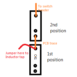
It also looks like only the second capacitor position is connected to the switch header, so if using the first capacitor position I must jumper across to the switch header.
There is also provision on the PCB for a pad and bypass switch, although I'll come to this later.
The only other important thing to notice is that there are no values for (almost) all of the components. This is because you will need to calculate them!!
Calculating component values
The documents I have linked to above give all the necessary information to calculate the C, R and L values. I have created a spreadsheet for myself to simplify things even further.
The first thing to do is decide upon resistor & potentiometer values. As I am wary of making mistakes and will be using Ians twin line amp for make up gain, I'll going to go with the standard configuration and values given by Ian.
The spreadsheet
I've created a spreadsheet so there is no need to faff around with doing calculations by hand and to allow me to play around with values without having to redo everything.
The spreadsheet is here:
https://docs.google.com/file/d/0B6LqEShkjOdRbm9EeFI0VWtTY00/edit?usp=sharing
For the RC filters, you simply add your desired corner frequency and it comes up with exact capacitor values. You can then add realistic capacitor values and see how this changes the frequency.
For the RCL filters, add your desired frequencies and 'Q' value and it comes up with the bandwith and exact inductance values required.
Then it gets a little tricky in terms of logistics. You will likely come up with a distinct inductance value for each frequency position. But inductors have at most 6 or 7 taps at predefined values.
So what you need to do, is take a look at inductor datasheets, like this one:
http://www.audiomaintenance.com/downloads/carnhill_design_guide.pdf
And choose inductors (that will fit on the PCB) that have the right range of taps for each filter section. You then need to put in the 'real' inductor value in the spreadsheet. The bandwidth will be recalculated and an exact capacitance value calculated. Again...there are only a certain number of capacitor values around, so you'll need to find the nearest match and put it in. The actual frequency will then be recalculated!!
So you can see, in theory, it is very easy to calculate the values required to get whatever frequency you want. But in practice, as there a limited number of C values readily available, and an even more limited number of inductance values, it will probably take a fair bit of playing around to get some 'real' component values coupled with some useful frequencies and bandwidths.
Phew! All the above is explained clearly in the spreadsheet.
So, I started by putting in values for the RC filters. As you can see from the spreadsheet, I started off with exact frequencies that relate to musical notes. There is even a musical note vs freq page on the second sheet.
But, I quickly got bored after realising that the limitations in capacitor values aren't going to allow for such precise frequency selection. So I quickly filled in the rest with a broad range of frequencies, trying to keep most detail in the mid-range (where most music happens!) while still providing a broad range of high cuts/boosts.
Luckily, with 7 filter sections this isn't so hard to do.
I filled in all 8 values for the RC filters, but it seems that 8 position switches aren't so easy to come by. Six position switches are readily made, so I may need to revisit this section.
I have not yet finished filling in the RLC section.
One thing to note is that each RLC section is in parallel with each other, so if frequencies overlap, instead of the boost/cut adding together, it will remain but be sharper (I hope I'm not making a mistake here.). What we should take from this is that you should not make the frequencies overlap!
Questions
There were a couple of things that I am struggling to get my head around in the pdf's provided for the project. These are mainly to do with the RLC sections:
[list type=decimal]
[*]R4 is referred to in the InductorCalc pdf as having a value of 2K2. I am having trouble relating this resistor to anything on the original schmatic or PCB. Is it Rcut1 and Rcut2? This is fairly critical as the inductor calculations are based on the sum of R4 and the source resistance.
[*]I am assuming that the source resistance of 150R as quoted in the InductorCalcs pdf would be the source resistance presented to the RLC filter stage from the previous stage, if wired in the standard configuration given by the UNIEQconfiguration PDF?
[*]As I uderstand it, the role of Rfix is to allow the parallel sections to still provide boost if one (or two) of them are switched to 'cut' mode. Does this mean that R6 should take the same value as VR6/VR8 (47K) ?
[*]The value of Rshelf is given as 220R if VR2 is 2K2. I find this gives a shelving frequency a decade above the cut. For high cut this seems a bit odd to me as the shelf will be largely inaudible (e.g. for a cut at 5K, the shelf is at 50K)...making it practically not much different to a non-shelving type. Have I got this wrong? Is there anything to be concerned about if raising the value of Rshelf?
[/list]
I have thus far not mentioned much about the resistors in the project, as I am simply taking the values offered by Ian . But I'll give a run through of what each of them are for reference. I'll leave blanks when I am unsure!
Firstly, you will see the resistance 'Rs' mentioned a lot in the RCcalcs PDF. If you don't read carefully first time round (like me), you will find yourself scouring the PCB for Rs (like me). It cannot be found. That is because Rs refers to the total resistance of the boost/cut pots in the RLC section. This forms one side of a potential divider, which is what makes the RC filters work.
With the value of the boost/cut pots - VR4, VR6, VR8 - at 47K, the total resistance is 15.7K - they are in parallel.
Now the rest:
So that is the start. Hopefully a useful resource for other UEQ builders and even more hopefully, I might get pointed in the right direction when I make (inevitable) mistakes!
I've got a number of boards from Ian, which I think should be enough to build the EQ:
2 * Universal EQ boards
1 Twin Line Amp board for makeup gain
3 * Lorlin switch mounting board
1 HT supply board.
Universal EQ
I'm starting by ignoring the power and gain sections for the moment and tackling the complex business of the EQ board. The universal EQ is seven passive filter sections on one board, which can be connected up however you like. There are four RC filter sections and three RCL filter sections. To read more about the possibilities, check out the original design thread:
http://www.groupdiy.com/index.php?topic=50484.0
There are 3 documents you need to read to have a hope of building the EQ boards:
Info on configuring a board and a 'standard' configuration using all sections:
http://www.ianbell.ukfsn.org/EzTubeMixer/docs/EzTubeMixer/UniversalEQ/UNIEQConfiguration.pdf
How to calculate values for the RC filters:
http://www.ianbell.ukfsn.org/EzTubeMixer/docs/EzTubeMixer/UniversalEQ/RCcalcs.pdf
How to calculate values for the RCL filters:
http://www.ianbell.ukfsn.org/EzTubeMixer/docs/EzTubeMixer/UniversalEQ/PCB/InductorCalcs.pdf
This project is a good step up from simply populating PCB's and linking them all up as it requires a lot more preparation and a little more understanding of schematics. A great learning exercise!
Configuration
The universal EQ can be configured pretty much how you want. At the end of the configuration document, Ian describes how to create some classic configurations like Pultec, 4 band Pultec and Helios 69.
The schematic drawn on page 3 shows the EQ wired up with all sections in use. 7 filter sections! Sounds exciting and if I have understood correctly, it is entirely possible and the values given throughout the documents relate to configuring the EQ in this manner. Which seems the easiest way to proceed!
Examining the PCB
I started by taking a look over the PCB and trying to relate this to the info in the docs above, which feature simplified schematics of the relevant sections for each doc.
First thing to notice is the possible number of frequency positions. Each RC filter can cater for 8 positions, and each RCL filter can have up to 12.
Thats a total of 68 positions we could be playing with - 68 capacitor values to calculate!
The RCL sections have two alternate positions for the capacitors, which seems confusing at first but after looking carefully and reading through the thread, it seems there is good reason.
If I understand correctly:
[list type=decimal]
[*]The inductor position fits a Carnhill or ChrioN footprint, specifically the VTB9050 and the tap points for this inductor have traces to the first capacitor positions. The silkscreen labelling also refers to this inductor.
[*] You may wish to use other inductors though. To do this, you would mount the capacitors in the alternate positions (the unlabelled ones). The first pin of the alternate positions and the last pin of the original capacitor positions are linked, so you can put a jumper from the inductor tap to the last pin of the original capacitor positions.
[/list]
Here is a crude drawing of what I mean.

It also looks like only the second capacitor position is connected to the switch header, so if using the first capacitor position I must jumper across to the switch header.
There is also provision on the PCB for a pad and bypass switch, although I'll come to this later.
The only other important thing to notice is that there are no values for (almost) all of the components. This is because you will need to calculate them!!
Calculating component values
The documents I have linked to above give all the necessary information to calculate the C, R and L values. I have created a spreadsheet for myself to simplify things even further.
The first thing to do is decide upon resistor & potentiometer values. As I am wary of making mistakes and will be using Ians twin line amp for make up gain, I'll going to go with the standard configuration and values given by Ian.
The spreadsheet
I've created a spreadsheet so there is no need to faff around with doing calculations by hand and to allow me to play around with values without having to redo everything.
The spreadsheet is here:
https://docs.google.com/file/d/0B6LqEShkjOdRbm9EeFI0VWtTY00/edit?usp=sharing
For the RC filters, you simply add your desired corner frequency and it comes up with exact capacitor values. You can then add realistic capacitor values and see how this changes the frequency.
For the RCL filters, add your desired frequencies and 'Q' value and it comes up with the bandwith and exact inductance values required.
Then it gets a little tricky in terms of logistics. You will likely come up with a distinct inductance value for each frequency position. But inductors have at most 6 or 7 taps at predefined values.
So what you need to do, is take a look at inductor datasheets, like this one:
http://www.audiomaintenance.com/downloads/carnhill_design_guide.pdf
And choose inductors (that will fit on the PCB) that have the right range of taps for each filter section. You then need to put in the 'real' inductor value in the spreadsheet. The bandwidth will be recalculated and an exact capacitance value calculated. Again...there are only a certain number of capacitor values around, so you'll need to find the nearest match and put it in. The actual frequency will then be recalculated!!
So you can see, in theory, it is very easy to calculate the values required to get whatever frequency you want. But in practice, as there a limited number of C values readily available, and an even more limited number of inductance values, it will probably take a fair bit of playing around to get some 'real' component values coupled with some useful frequencies and bandwidths.
Phew! All the above is explained clearly in the spreadsheet.
So, I started by putting in values for the RC filters. As you can see from the spreadsheet, I started off with exact frequencies that relate to musical notes. There is even a musical note vs freq page on the second sheet.
But, I quickly got bored after realising that the limitations in capacitor values aren't going to allow for such precise frequency selection. So I quickly filled in the rest with a broad range of frequencies, trying to keep most detail in the mid-range (where most music happens!) while still providing a broad range of high cuts/boosts.
Luckily, with 7 filter sections this isn't so hard to do.
I filled in all 8 values for the RC filters, but it seems that 8 position switches aren't so easy to come by. Six position switches are readily made, so I may need to revisit this section.
I have not yet finished filling in the RLC section.
One thing to note is that each RLC section is in parallel with each other, so if frequencies overlap, instead of the boost/cut adding together, it will remain but be sharper (I hope I'm not making a mistake here.). What we should take from this is that you should not make the frequencies overlap!
Questions
There were a couple of things that I am struggling to get my head around in the pdf's provided for the project. These are mainly to do with the RLC sections:
[list type=decimal]
[*]R4 is referred to in the InductorCalc pdf as having a value of 2K2. I am having trouble relating this resistor to anything on the original schmatic or PCB. Is it Rcut1 and Rcut2? This is fairly critical as the inductor calculations are based on the sum of R4 and the source resistance.
[*]I am assuming that the source resistance of 150R as quoted in the InductorCalcs pdf would be the source resistance presented to the RLC filter stage from the previous stage, if wired in the standard configuration given by the UNIEQconfiguration PDF?
[*]As I uderstand it, the role of Rfix is to allow the parallel sections to still provide boost if one (or two) of them are switched to 'cut' mode. Does this mean that R6 should take the same value as VR6/VR8 (47K) ?
[*]The value of Rshelf is given as 220R if VR2 is 2K2. I find this gives a shelving frequency a decade above the cut. For high cut this seems a bit odd to me as the shelf will be largely inaudible (e.g. for a cut at 5K, the shelf is at 50K)...making it practically not much different to a non-shelving type. Have I got this wrong? Is there anything to be concerned about if raising the value of Rshelf?
[/list]
I have thus far not mentioned much about the resistors in the project, as I am simply taking the values offered by Ian
. But I'll give a run through of what each of them are for reference. I'll leave blanks when I am unsure!Firstly, you will see the resistance 'Rs' mentioned a lot in the RCcalcs PDF. If you don't read carefully first time round (like me), you will find yourself scouring the PCB for Rs (like me). It cannot be found. That is because Rs refers to the total resistance of the boost/cut pots in the RLC section. This forms one side of a potential divider, which is what makes the RC filters work.
With the value of the boost/cut pots - VR4, VR6, VR8 - at 47K, the total resistance is 15.7K - they are in parallel.
Now the rest:
- VR1 220K: for Low Shelf Cut
- VR2 2K2: Boost/Cut for High Shelf
- VR3 22K: for Low Boost
- VR4 47K: for High boost
- VR5 4K7: Q for high boost
- VR6 47K: Boost/Cut for Low Mid
- VR7 4K7: Q for low mid
- VR8 47K: Boost/Cut for High mid
- VR9 4K7: Q for High mid
- Rshelf 220R(?): Turns the relevant RC filters into shelving types.
- Rbump 27K: Raises the low shelf cut frequency so that along with the low boost, the classic pultec 'bump' is obtained
- Rp: Entirely optional and would serve to change the non-shelving Low Cut into a shelving type (like Rshelf). If you are using the Low Shelf section, this is probably redundant
- Rfix: unsure of value
- Rcut: unsure of value
So that is the start. Hopefully a useful resource for other UEQ builders and even more hopefully, I might get pointed in the right direction when I make (inevitable) mistakes!