Nady TCM1050 Mod (T-Bone SCT 2000)

GroupDIY Audio Forum

Help Support GroupDIY Audio Forum:

This site may earn a commission from merchant affiliate links, including eBay, Amazon, and others.

Maliq

Well-known member
Joined
Apr 23, 2012
Messages
65
Hey Folks, I'm new here..and i'm still a NOOB so bare with me :-\ it seems like this forum is my last hope to get some answers..

I try to brake the situation down real quick, I want to mod my T-Bone SCT 2000 Microphone, (its exactly the same mic like the Nady TCM1050). I'm not scared to change the Capsule, but I think that i need to change the Output Transformer too..I've also talked to WIMA Caps here in Germany just in case that i need some caps.. but I'll be honest with you guys, i've never hold a soldering iron in my hands..ok I can learn, so I can only hope that you answer some Questions for me. I'm very facinated by the work you guys do and all I wanne do is at least try to mod my mic one time..if i fail..well ,then thats it for my mic ;).. (at least i managed it to change the Tube allready to a Mullard 12At7U). Anyway here are my Questions.

1. Since this Microphone got his own Power supply, I guess the Output Transformer need to be different then on a Phantom powered Condenser mic right?

2. Is there a good Output transformer that you can recommend?

3. Is it true that  Tube mics with a PSU need different output transformers then Phantom powered Mics (I worry a lot about all the different voltages going on inside the mic, and that i can "kill" the mic when i hook up a cable wrong, or use the wrong transformer)

3. How do you know what all the Caps are doing inside the Mic, I mean they all look kinda similar, some are red, some round and blue, and some look like Black "Tubes"..do i need to get a Data sheed about the electricity and all that for the mic to see which cap is doing what? and does it make sense to replace them with WIMA caps?

Sorry..if this was too much for the beginning, but I feel a lilttle lost..Most important to me is to change the Capsule, maybe to a RK-47 Capsule and to change the Output Transformer..
Here are some "Inside pictures" of the Mic..Hope you can help me..Thanks for your time :-[

abpeh1.jpg


wtzuck.jpg


20fpb40.jpg


msdj74.jpg


ab5ws6.jpg

 
Ok, i guess i read so damn much now about caps, and what they do..that i at least understand a little of it, and i must say, i would not remove a cap until somebody tell me you can get this and this cap at R3, C4 whatever and solder it..i'm to scared that the whole mic will explode if i do something wrong..and when i see lists like this about caps http://www.wima.com/EN/tpl_products_pcm5_overview.htm then it really scares the sh** outta me cause i really know nothing about it. So I guess I stay with Changing the capsule and changing the Output Transformer.. as soon as somebody can tell me which Output i can use for this mic i'll get it.. and if somebody say look if you remove this and this cap with this and this it'll improve your mic..i'll give that a try too.. Thanks
 
Well...it's been the modus operandi here to help folks along, but not give them the answers outright, so they learn something. You've done some good research about caps, so as someone who was in your shoes just a few years ago, here's some advice that's already all over this forum, but is easy to overlook...
The capsule is responsible for 90 percent of the overall tone of the mic, and there's not much you can do to correct the sound of a junk capsule. Some of the 1050s have decent capsules, so maybe you lucked out. How does it sound? Do both capsules sound close in tone when you put it in figure 8 mode? A good capsule will cost more than the mic cost you in the first place, and if you've never changed one before it can get dicey. Get a RK47 first for @$100 (or talk to Blue Jinn, he's got a contact{shhhhh!!}, and learn with a less expensive, but better than stock alternative.
I put a C-12 clone in mine and it's a much better mic, tho I'm sure it would sound even better with a more expensive capsule. Maybe some day I'll feel that wealthy....
What tube is in there? If it's a 12AX7, try a 12AT7 instead and see what you think.
Changing capacitors won't change the sound too much, so concentrate on the big stuff until you are more aware of why you are doing what you are doing. The caps are OK in this mic, tho one in particular could be swapped for a different kind, and sound better. A hint... it's the one connected directly to the output transformer (OT)in the mic.
I've been working on mine with the original OT, which some folks say is fine for the original circuit, especially with the proper tube for the mic.
Do you have the schematic for the mic, and can you read a schematic? If no to both, then let me know, and I'll pop one up here Mics are relatively simple circuits, and a good place to start with all that.
This is essentially the Apex 460 circuit, and there is LOTS of info about this all over the web.
 
Thanks so far, I need to try that out with the Figure 8 Pattern, like I sayed my Mic is the Mic shown above in the Pics. Its a T-Bone SCT 2000
a.provider,m.202345,mod.media,th.thumbs3,s.pictures.jpg
but it seems very similar to the Nady TCM 1050. They sell it here in Germany.

Ok, yes I figured out that most of the Sound comes from the Capsule (and I thought Output Transformer too).  i had the RK-47 in my Mind.. so you talk about the Cap to the Output Transformer..hmm, ok seems like R9 is connected to the Blue wire of the Output Transformer. I also think the Big Round "Tube" Cap on C8 or whatever is called is connected to the Red wire on the Output.. :-\ but then again C9 and C 10 seems to connect to the Green and black wire of the Output...uhm..so theres a lot..
If I would replace Caps, can I do harm to the mic when the Cap got a different Voltage flow then the Original One, or if soldering it the wrong way? ..(I guess so)

I might understand a lil bit of schematics cause we did some schematics when I became an Audio Engineer (but that was a schematic about Signal flow inside a Console)..and no I have no Schematics of the Mic so far

Thank you


Here's the schematic for the Apex 460. It should match your mic and PSU, but it's best to check it and make sure.
   
  Yes, you are right about the capacitors connected to the OT. Only 1 of them is what we want to change, because it is in the signal path. The other two are part of a RF filter network. Many people remove these. I'm pretty sure I did on my own 1050.
  So, the question is: which of these caps (C8, C9, C10) is DIRECTLY in the path of the signal? The schematic should make this clear.
  Let's replace it with a nice polyester or metal film capacitor of the same value, and equal or greater voltage rating. These caps have no polarity, so there is no need to worry about that.
  The sound difference will be small, but improved. Usually a little smoother. Less gritty.
 
    Yes, if you replace electrolytics, you need to be sure that the polarity is correct. But we want to get the electrolytics out of the signal path.
    If I remember correctly, this cap is the only electrolytic in the signal path. The others are for power filtering or blocking. Many people like to replace them with better electrolytic caps, and even say they hear improvements, but I recommend leaving them alone for now. Why take chances on damaging the circuit board or traces?
  For now, just make the one change, and see if you can hear the difference. Maybe even make some recordings before and after.
Have fun!


....and if it has a 12AX7, I'd really recommend a 12AT7 instead.
 

Attachments

  • Apex460.pdf
    250.3 KB
Thanks so far...I'm scared now... :eek: :eek:

ok, I guess you mean that I should replace C8? cause its in the Signal path (I just guess it cause it coming from the Tube) ???

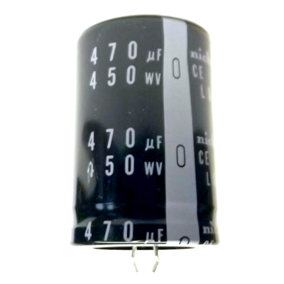
the others are just connected to the OT..the thing / Cap that I should replace looks similar to this one right??

Elko470_450.jpg


God I'm scared..so i took one another picture of my mic and i figured out, on your Schematics it says 1uf/450V but in my Mic this "piece" got something writen on it 1uf / 400V So its 50V less...uhmm (like i sayed i dont know nuthing bout those caps yet)

I marked the Cap that I should replace tell me if i'm right, feels like i'm back in school, even if i'm scared as Hell ;D.. Can you recommend a Cap that I should get? i mean when i search for 1uf 450V or 400V on google..i get strange results...I don't know seems like Wima make "other Caps", can you recommend some good Caps..so i get a feeling like what is good.. I allready know about capsules and got links for good OT but not for "Caps"

okbbqc.jpg


I need to buy a soldering iron also soon...but thats another thing not important now..I used to build Aircraft models when i was young so i'm patient hahaah hope this helps


C8... That's the culprit.
Polypropylene, polyester, metal film. They all have slightly different sound, and folks will argue that one is better than the other, but all are better than an electrolytic...Most importantly, it must fit in the space provided.
You can spend lots on capacitors with magical, mystical qualities about them, or just get something easy. I think you'll be fine with a 400V rating. 450 is better, if you find it. Maybe someone in Germany will recommend a good supplier.

See that shiny barrel-shaped capacitor that says "1000P" on it? That's the first cap in the signal path, right after the capsule. It's fine. Leave it alone. In many mics you will see this arrangement of this cap and two 1 Gigohm resistors. In this mic they got it right. That's a polypropylene capacitor.
C8 is the last cap in the path, and it's messing up the sound.

Spend your cash on a good soldering iron, if you are starting down this path. You'll thank me later. Maybe one of those solder station things with the adjustable temperature control. Hakko makes one for about $100 US.

Don't be scared. The hard part is getting the old cap out cleanly. work with a plastic bag over the capsule/grill so solder doesn't splash in there. This is where a good iron is worth the money. Maybe take the tube out first. Try to touch the actual circuit board as little as possible. If you haven't soldered in a while, a little practice on some junk boards wouldn't hurt.

Here's a photo of the C8 metal film cap in my 1050...
 

Attachments

  • 1050 almost there.jpg
    1050 almost there.jpg
    162.8 KB
ok good to know, I try to take a look at Wima, i figured out they got alot of stuff, but we got alot of suppilers outhere..so i'll try to find a 400V/450V Cap, one thing that still puzzles me is:

Should the AC Voltage be 400V/450 or the DC Voltage? cause you can choose on the wima page..and i'm still scared that i buy a wrong one and the mic explodes ??? haha (no its not funny)
Also there is a Tolarance like 5%,10%,20% is that important or doesn't matter? I figured it need to be 1uF 400V or 450V (like the schematics say)

I found a Cap

Radial polyprop cap
1uF 450V
Tolerance=10%
12.6mm
Manufactures: Panasonic

r7269972_01.jpg


or

400v-1uf-105j-metallisierten-polypropylenfolienkondensatoren-cbb22-154212n.jpg


or 400Vdc
174_997929c755bb61d34c9892fbe2272313_4.jpg


or wima... i guess no matter..hopefully

Good??

I see the 1000P on top yes...sure i'll leave it alone, ah and by the way I allready got a British Mullard 12AT7U inside
Yes I'll take a look at a good Soldering iron of course..and i heard about the thing with the Plastik Bag and i'll take the Tube out before i start soldering

So i also figured that when a cap is a lil "bigger" and don't fit, you try to find a place somewhere near and use some little wires to connect the Cap wit the Board, (like you did on your picture) so is there something i need to know about those lil wires? material or something else?

Thank you


Wima is good, but any of those are better than what it has now.
Almost anything you get will be bigger than what is already in there. You will need to be creative to make it fit. I just put shrink tubing around the leads to the cap so nothing gets shorted. It is hard to get some of the barrel-shaped caps in there. The flat ones would be easier.

I think the voltage is AC there, as DC voltage does not pass thru a transformer.  I can't give you a very smart answer. You could open up the mic and measure with a meter while it is powered. Naturally, be careful.
Looking at my own mic, I see the cap has a 400v rating. I probably read in some thread somewhere that this was OK, or I wouldn't have done it.
With that tube, you have taken this mic about as far as it can go without changing the capsule, once you change C8.

Here is an interesting website about this type of circuit.
http://www.foxaudioresearch.ca/The460secret.htm
As always, don't believe everything you read on the subject. There are SO MANY threads about this circuit. Some people change it to a C12-style plate out. My decision was to leave mine as is, since the circuit is unusual. I just put a better capsule in it to see how it sounds, and I like it.

Then I took the old capsule, and made another mic with it. :)
It never ends...

Later, I will get a 460, and make a C12 clone with the same type of capsule I put in my 1050.
It's always possible to upgrade to a high-end capsule once I find which mic sounds best to me.
Sounds like you're almost ready to do this...
Careful. You'll get hooked, and the next thing you know, you'll have 30 mics....
 
Ok, yes i'll get one of the flat one Caps.. so what would happen if you solder a DC instead of an AC accidently, could this kill the mic? or would it just lead that the cap is "not function" ???

and once again, what would happen if you solder the Cap the wrong way, left right / right left? I guess cap C8 got nothing to do with polarization -/+ but i'm not sure about that.. ??

also, how you figure out where + and - is on other caps or for the Future? also with measuring?

Meassure on the mic while its powered...wow then i have to be really really carefull, if i touch it one time then thats it for me, not for the mic.. What piece of Equipment do i need to measure?  :eek:

Thanks..seems like we getting somewhere

 
AFAIK, all caps will work in AC or DC voltage. It's just that the ratings are different depending on whether you put AC or DC thru them.

Polarity is important on electrolytic, and some (or all) tantalum caps. Polypro, polyester, metal film are "non-polar" and it doesn't matter which way they go.
It is important to get the polarity right on "polar" caps. They will eventually fail or even explode if installed "backwards".
You will know if a cap is "polar' because it will show a "+" and/or "-". There may be a "+" on the circuit board to mark the polarity, but when installing a "non-polar" cap in that spot, it can go either way.

You have to be careful when measuring an open mic, but only certain places in the mic are dangerous. Phantom powered, non-tube mics should not have enough voltage to be dangerous. The 1050 has high voltages tho, so you are right to be careful.

Measure with a digital multi-meter or DMM. They are less expensive than a a good soldering iron, and very useful. With one, you can measure resistance, voltage, and continuity, as well as some other features.
I usually connect the meter using jumpers, and then turn on the mic so that I am not touching the mic while measuring, but once you are comfortable, and know where NOT to touch, it is easy to connect to a ground point with jumpers, and then carefully move the probe to measure different places.

For this cap replacement, just solder the cap and make sure the connections are good. You don't need a meter to do this, but eventually, you will want one if you get hooked on DIY...
 
tchgtr said:
...but once you are comfortable, and know where NOT to touch, it is easy to connect to a ground point with jumpers, and then carefully move the probe to measure different places.

I want to add that when doing this kind of of thing with power on, especially when working inside the PSU, always keep the other hand behind your back.
 
Thanks pasarski. That's a very good technique to keep from getting hurt. I always use that when looking into AC house wiring.
...and give a PSU, or any high-voltage device, a little time after turning it off before working on it cold. Caps can store power for a while.
 
Ok thats good to know about the polarity, cause 95% of the time i'll use caps without polarity issues, and when i replace C8 (Electrolyt) with an metall Polypropylen-Film-Cap (or something similar) I can install it either way..

There's a good Electro store in my city, i know these guys and they life and breath electric ;D, i talked to them on the phone today, they don't know much bout mics but all about electronics and soldering.
I might take my mic with me so maybe they can show me how to measure and how to read a DMM correctly once, I figured that i need a DDM that can measure up Voltage to... uhm 600V i guess..the higher Voltage it can measure (or take) the more expensive it seems..but yea i'll not need it for this mic but i can see it for later allready..

That lead me to another Question: Is it also possible to figure out the "Signal Path" if there's no schematics available..maybe with measuring too? If the answer is to long no worrys its not important for me right now i'm just curious..and since we're not only record rap vocals, also pop and Female Singers.. I might have a mic for the Future that i allready want to mod too (later)...

Thanks so far, this Forum is allready something spezial to me..my mind start to calm down since i'm here and i don't care much about the whole microphone madness nomore...cause somehow, any mic is kinda the same..just different caps, different Capsules, different OT..but thats about it..kinda..


Can I suggest that before you start on your mike, you get a LOT of practice with soldering.

You need a good iron with a fine tip.  And get some thin old fashion solder with LEAD in it rather than the new fangled ROHS stuff.

Don't even think of taking an iron to your mike until you can make good clean solder joints within seconds.

The old pencil ANTEX irons used to come with a little booklet on soldering technique with pics of what is good and what is bad.  Anyone know anything similar on the www today?
 
I would suggest an electronics grade silver-bearing solder. It only has a liquid (molten) and solid state. Unlike normal solders that have a liquid, paste, and solid state. If you move the soldered connection while it is cooling (during the paste state), it will create a cold solder. The silver-bearing stuff doesn't suffer from this ailment. It also doesn't need flux for proper solder flow. It may cost more, but the lack of stress and cold joints is well worth it.
I wish someone would have told me about this when I started repairing my own guitar cables. I'd have a lot more guitar cables laying around these days...
 
yap, thanks for the tips, I'll definitely make sure that i get a good iron, like i sayed these guys from the Store i was talkin 'bout earlier know alot about all this and they will probably sell me a good soldering iron or tell me where i can get a very good one.

I also got a few old broken CD roms drives laying around in my studio so i'll "burn" them a lil bit to practise..

so if possible can someone answer what you guys do when there's no Schematics available? if you see the borads, and the connections, can you figure out where the signal path is?? I guess so but just asking..

Thanks
 
You start to recognize certain repeated patterns, like the small cap attached to 2 1G resistors where the capsule meets the circuit board, or the cap attached to the OT.
But we really like to see schemos around here, and they are usually to be found somewhere in this day and age. If not, someone will often trace out something as simple as a mic circuit.
 
It took a few days cause i was pretty bussy with some work in our Studio but i'm back to my "soldering" work  :), i bought a soldering iron with a very small tip, and i tryed it out on a broken cd-rom..
Today i tryed to de-solder the Electrolyt (C8) on the tube mic..no success so far.. any good tips on desoldering it..i don't want to brake it, also i figured that the Electrolyt gets pretty hot when i molten the soldering joints, but they turn solid in less then a second so i can't molten both joints to pull it out with a pincher.. you guys got some ideas... :-\ :-[
 
For removing individual components from a through-hole PCB (where the component pins extend through holes in the board to the opposite side, rather than surface mount), desoldering braid (e.g., Solder-Wick) is the easiest way. Make sure your soldering iron tip is clean and tinned, and don't linger too long on any one pad.

Here's an example of the technique from YouTube.

http://www.youtube.com/watch?v=LL_1VHCCyVI

If the wick doesn't drink up the solder when it melts, you might need to "prime" it with a dab of fresh solder, to get some flux on the copper braid.
 
Back
Top