[BUILD] CAPI VP28~500 Series~2-Stage Preamp~Official Support Thread

GroupDIY Audio Forum

Help Support GroupDIY Audio Forum:

This site may earn a commission from merchant affiliate links, including eBay, Amazon, and others.
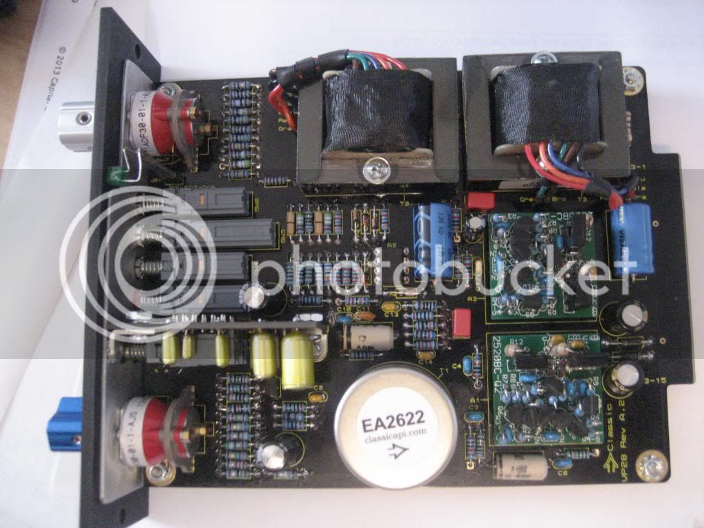
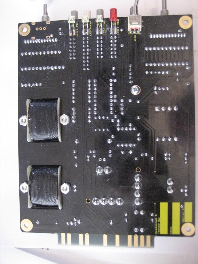
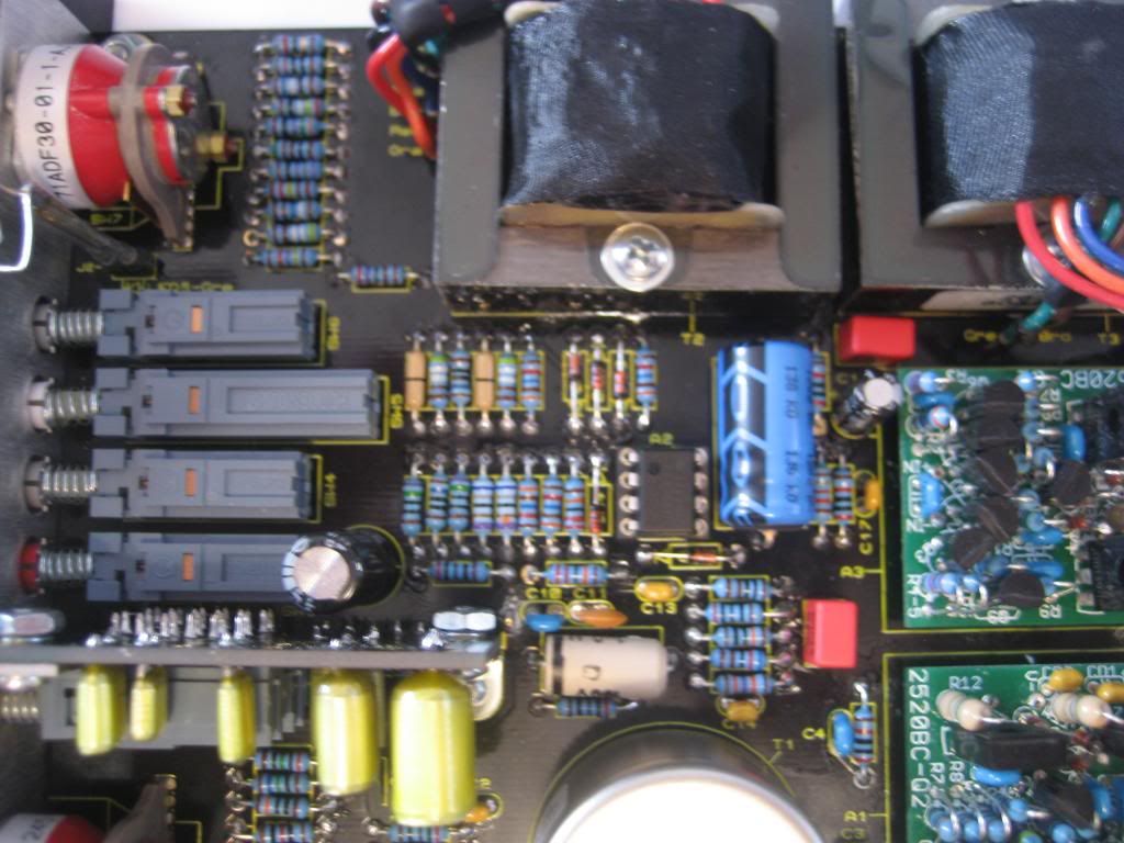
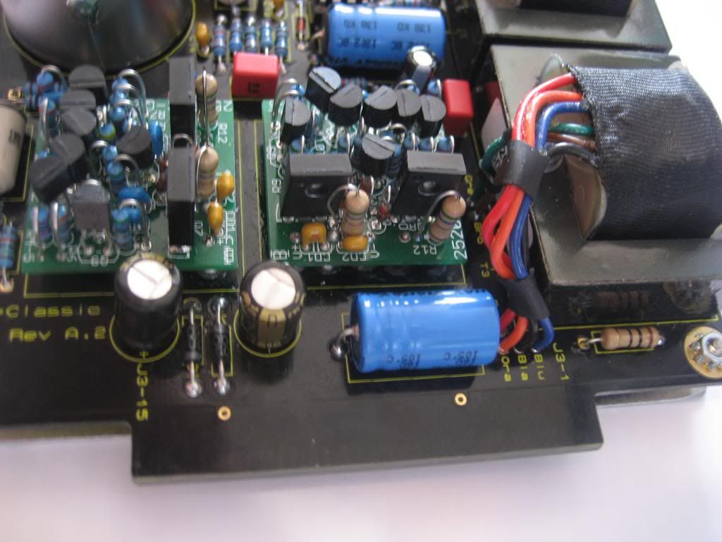
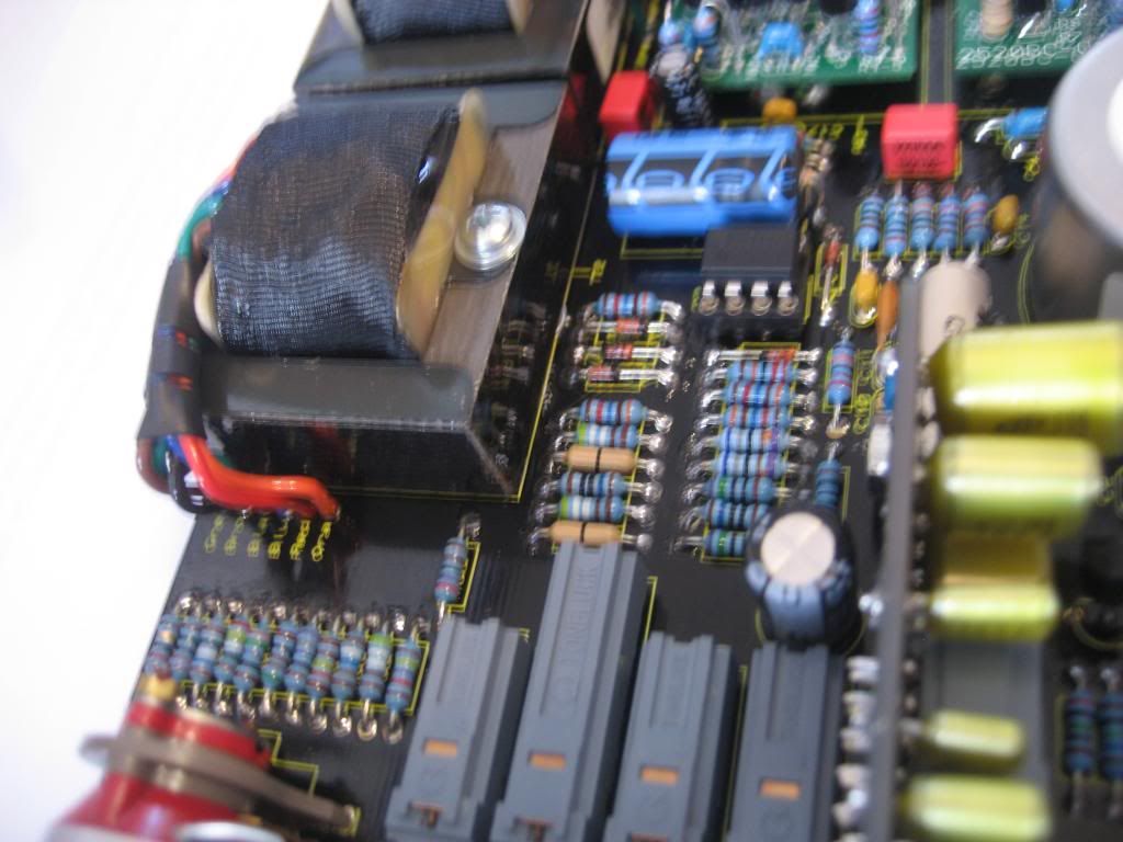
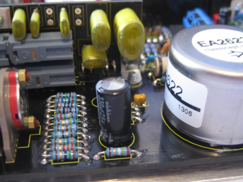
Got my VP28 finished yesterday, very easy to build (thanks to Jeff and Chunger, great instructions!), looking forward to giving it some use!

Edit: forgot to mention that i snapped the lens part of the Signal LED off whilst trying to get it into the hole and get the leads in the correct place, so just be a little more careful than I was with it! The LED still works, but doesn't sit in the hole anymore.
 

Attachments

  • BAum3bvCQAAiq4t.jpg-large.jpeg
    BAum3bvCQAAiq4t.jpg-large.jpeg
    60.2 KB · Views: 55
Hey,

I thought I'd share the sorting sheets I've made for the VP28 builds. Heavily influenced by the ones Chunger have made in his pictorial, obviously  :)

They are made in the European A4 format. Hit me up for the excel version if you want to make it fit the american standard for printing.

VP28 gain and fader resistors.
 

Attachments

  • VP28 gain and fader resistors - A4.pdf
    166.5 KB · Views: 68
VP28 Main PCB and 553 HPF PCB Capacitors
 

Attachments

  • VP28 Main PCB and 553 HPF PCB Capacitors - A4.pdf
    167.3 KB · Views: 51
just finished the second vp28, as always a sheer joy
gave them a small ride yesterday with mono beats from my machinedrum, one fitted with ppa germanium at input and  ppa 2050e in the out,
the other one with same opamp at output but with ppa 2055 fet input.
the vp´s really totaly blew me in a way i had not expected.. :eek: ;D
it sounds so nice to drive the first stage ... like having a really fat old console here..have to change my plans for my second 511x rack.. don´t need
more comps , just more vp´s !!
ok i have to test them out with the reddots and melcors  i have around, but so far the above combos are sounding very nice. the germ input is slightly more forward sounding with nice second (?)
harmonics, will keep two for drumbuss , the fet input is sounding a little more balanced to my ears, would like to try them on mixbuss i think,
for sure the vp makes more difference to the overall sound  than the opamps
thanks jeff for this cool units and congrats to be the inventor of modular 500/511x console sound in one box !
..now i have to earn some money for more of them ;)

axel
axel
 
***UPDATED VP28 Main PCB and 553 HPF PCB Capacitors sheet***
 

Attachments

  • VP28 Main PCB and 553 HPF PCB Capacitors - A4.pdf
    168 KB · Views: 68
We've built a few VP28's - they are indeed excellent sounding and have a great feature set that makes them extremely useful.

First, a quick question - is there any protection from phantom power for line devices if inadvertently connected? I can always check with my MM, but I'm not in my work room right now.

Bigger question - two of the most recent 8 we built have lower gain or output. Is this something that has a common cause? Ops are good. Checked that knob position was accurate and it was.

Waiting for replacement oscilloscope, so I'm a little hand-tied for the rest of this week, but solder sucker and iron are ready for action now. :-D

Thanks!

BTW Great Thread!
 
analogdays said:
....is there any protection from phantom power for line devices if inadvertently connected? I can always check with my MM, but I'm not in my work room right now....
No guardrails on this road. Proceed with caution. No different than caution with some ribbons.

....Bigger question - two of the most recent 8 we built have lower gain or output. Is this something that has a common cause? Ops are good. Checked that knob position was accurate and it was.
First, how much lower gain?

I would rule out rack slots, associated cabling, converter settings, patchbay, on and on. The next thing to look at are always the opamps. Swap them with one of the earlier units and see what happens. I would also look at 2623-1 wiring. Seems odd that both of the last 2 are equally lower (are they exactly equal?). Makes me also think it could be an accidental resistor swapping that occurred on both of the last 2 units.
 
You're fast!

That's what I'd guessed.

On the level question:
I'd guess 10-15dB lower. Useable, but not as much output as normal.  ???

 
Something is definitely wrong with the builds. Are the 2 latest ones the same as far as lower level?
 
Just finished one vp28. Lots of gain! Big sound! Thanks jeff! Only one problem.... When i turn phantom on the led does not work and all the others go off. The green  (signal) led is not work too.. Any tips?
 
Yes, the phantom LED is in backwards. All the LED's are in a series string. The phantom LED is first inn this series so when you engage the switch, the voltage to the string stops at the red LED because it's backwards.
 
Yes, the best is to refer to the gar1731 help thread. I think you will find what you are looking for. It's probably either the diode orientation and/or the larger BD transistors.
 
Symptom: Just built a VP28 in a DIY 51x 11-space rack w/ floor power supply. Aside from working LEDs, unit appears to be dead. No signal and signal LED is dark. I did get a little faint signal with lots of noise when I fed it a line level signal direct from my converters with the fader and gain all the way. Opamps are pre-assembled GAR2502s.

Troubleshooting so far:
Checked all solder joints for shorts, all look ok to me
Checked diode and caps for polarity, all good
Checked xfrm wiring, all good
Checked LEDs - phase LED backwards, now fixed
C1 Cap has a slight rounding on the top, like it was installed in rev

Any help would be incredibly appreciated. Please someone tell me I did something stupid I can fix easy. I don't want to be stuck with a $400 brick

Thanks

IMG_1334.jpg

IMG_1345.jpg

IMG_1343.jpg

IMG_1338.jpg

IMG_1337.jpg

IMG_1336.jpg

IMG_1335.jpg

 
Mrosso,

I noticed you said "Checked all solder joints for shorts, all look ok to me", did you do a continuity test down the line? I've had "perfect looking" solder points be cold,..recently.

let us know
 
First off, great job posting pictures - makes it easy for people to try to help.
So looking over the pics that cap does looks bad.
Not sure how it would have gotten fried though. Is your 51x rack and psu verified to be good?
You shouldn't have more than 25v even present on the vp28 to fry that cap, unless the psu was to hot.
I would plan to replace it, but I am guessing that is a DC blocking cap for the gain stage, so it shouldn't kill all your signal.

As you say it is hard to trace out without having a schematic, but, you can narrow things down pretty easily.
And the circuit is pretty simple so it is possible to do some tests.
Do you have any other DOAs you can swap, or do you just have the pair?
Verify the voltages from the psu?
When troubleshooting, I always try to be methodical and eliminate things that could be wrong.
What test equipment do you have?


Latest posts

Back
Top