[BUILD] CAPI 511-VPR~Filtered 500 Series 11 Space Rack~Official Support Thread

GroupDIY Audio Forum

Help Support GroupDIY Audio Forum:

This site may earn a commission from merchant affiliate links, including eBay, Amazon, and others.

jsteiger

Well-known member
White Market Member
Joined
Apr 11, 2008
Messages
3,585
Location
Nashville TN
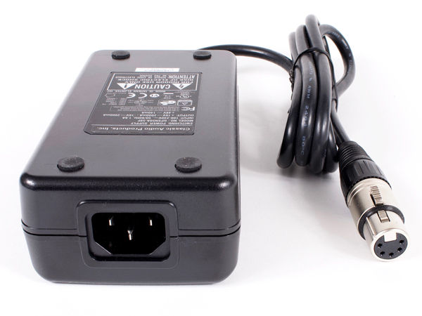
Hey folks, I have just finished up the Pictorial Build Guide for my new style 11 space rack kits. This latest version has LC filtering on the rear of the 9-11 backplane. The filtering is mainly for the new cost affordable switch mode PSU that I just added to the store. PS: there is no harm in using the filtered rack with a linear PSU.

511 Rack Pictorial Build Guide is located here:
http://capi-gear.com/catalog/Build_511_Rack.php

Details and automated checkout can be had here:
http://capi-gear.com/catalog/index.php?cPath=87_89_182

The new VPR Switch Mode PSU can be found here:
http://capi-gear.com/catalog/product_info.php?cPath=87_89_182&products_id=567

Since this is the official support thread, please post all questions, components and/or build problems here. I will do my best to help you get things sorted.
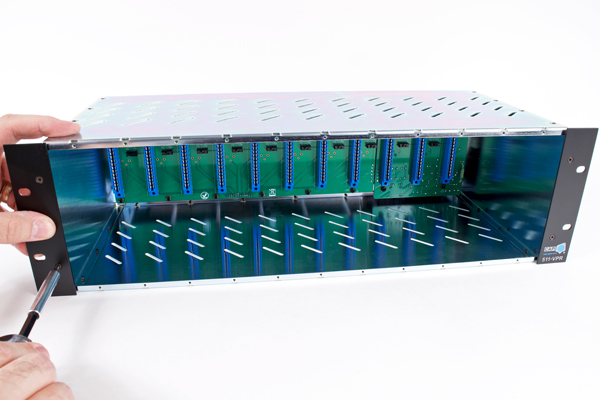
11-gdiy.jpg


SMPS-2-gdiy.jpg


Cheers, Jeff
 
Hi

I recently got the db25 kit and I put it together last night but it doesn't appear to be working right

I have a pair of diyre colour modules in there and the lights on them just slowly pulse and I don't get any signal. The power supply's blue light comes is on until I plug it into the rack at which point it goes off

I have got a video I can show you but I'm not sure how to post it

Can anyone help?

Cheers
 
keeeth said:
Hi

I recently got the db25 kit and I put it together last night but it doesn't appear to be working right

I have a pair of diyre colour modules in there and the lights on them just slowly pulse and I don't get any signal. The power supply's blue light comes is on until I plug it into the rack at which point it goes off

I have got a video I can show you but I'm not sure how to post it

Can anyone help?

Cheers
What are the DC voltages in the rack? Its possible you have a backwards capacitor in the backplane filter section.
 
keeeth said:
Hi

I recently got the db25 kit and I put it together last night but it doesn't appear to be working right

I have a pair of diyre colour modules in there and the lights on them just slowly pulse and I don't get any signal. The power supply's blue light comes is on until I plug it into the rack at which point it goes off

I have got a video I can show you but I'm not sure how to post it

Can anyone help?

Cheers

DIYRE support checking in here. Once you've checked the power rails on the rack itself, please check the voltages on the +16v and -16v test pads of the Palette. If the power voltages are fine at the rack but messed up at the Palette test points it could be that something is tripping the fuses F1 and F2 and we need to go searching for a short circuit in your build.
 
camarada78 said:
What are the pin voltages in case I want to build a Linear PSU for it?
For what? A standard 500 series rack? The pinout tables are in the back of the Floor Box build guide.
 
john12ax7 said:
Hi Jeff,

That power supply looks like it could be useful for various other projects. Is there a recommended filter to use for it?
I am actually cooking up a standalone filter that goes in my new clamshell extrusion. It is a little ways off.
 
I was wondering about the possibility to install db25 connectors on a xlr rack, since its the same pcb, that could be a nice option only need to makes holes for the connectors on the back plate.

jy
 
noiro said:
I was wondering about the possibility to install db25 connectors on a xlr rack, since its the same pcb, that could be a nice option only need to makes holes for the connectors on the back plate.

jy
Yes it could be done. I considered it from the beginning but did not want to stock a 3rd rear panel or make folks buy parts they'd never use. Not sure of the physical layout with the flex PCBs I have. It may put the DB25s into a bad position relative to the XLRs.
 
I saw that, you are right one of them is too short to be put below the xlrs, what about one plate mod (xlr) that have the db25 holes but with a mask type of mini plate with 2 screws, perhaps that possible, anyway its an amazing rack already !
 
rachansky said:
Well...I would check DC voltages at the proper pins. Unless the PSU is way off I cannot think of anything that would cause these things. The rack is a very straight forward piece of gear. Maybe there's some kind of short in the PSU cable.
 
rachansky said:
Ok so the psu outputs are are reading +/- 16.8V and 48.2V.

In the rack however I am only getting -13.2v on the negative rail. (This is with 7 modules loaded). The other outputs are in line with the psu output.

Does this spark any ideas?
What is it with no modules loaded? I would not install any modules without figuring out what is up with the negative V rail.
 
Ok so I've reflowed solder and checked to make sure that the regulator wasn't installed too tightly but here is my scenario with 7 modules loaded and an output of approx. 14.5 V on the -16V rail, and +16.7V on the 16V rail

From the toroidal transformer into the board JP3-5&6  voltage =-2.72V
JP3 -7&8 are 11.67V
at the +16V regulator (starting on the side closest to the leds) voltages are 15, 21, and 23V respectively

at the -16V regulator (starting on the side closest to the leds) voltages are -1, 0 and 9V respectively

Beginnning inboard and working outboard ( I hope that makes sense) through c39 - c42 I have 11.6,  23.4, 23.4, 11.6, 11.6, 0, 0,
11.6 (volts in all cases)

Beginning inboard and working outboard through c30 to c33 I have -2.72, 9, 9, -2.72, -14.5, -14.5, -2.72 again volts in all cases.

I'm really hoping this info is enough to give me some direction here. If not I may just bow out and buy another power supply.
 
This looks like a Floor Box PSU issue not a 511 rack. I don't think we should be posting about this on this particular build thread. I would suggest deleting these posts and looking at the Floor Box support thread. Please read thru it before posting as you may find the solution you need already posted.
 
Fair enough. The thought had occurred to me but I wanted to make sure we had continuity through here. I spent a good chunk of the morning reading through the floor box forum chain but I didnt find anything remotely similiar.

Thanks for your time sir!
 
Hello, I have an odd issue.  I went to load a module in my 3rd space today after never using it in the past and had no audio passing.  So, figuring I messed something up I disassembled it and found that only on slot 3 my input pin 2 (pin 10 on the edge connector) goes to ground and this is after removing the XLR connectors and edge connector.  Am I going crazy or is there possibly and issue with the pcb board? 
 

Latest posts

Back
Top