C12 Build from scratch

GroupDIY Audio Forum

Help Support GroupDIY Audio Forum:

This site may earn a commission from merchant affiliate links, including eBay, Amazon, and others.

muffy1975

Well-known member
Joined
Mar 21, 2006
Messages
330
Location
UK
Guys,

I have surfed around the group hug/diy site and can't find anyone laying out how to build an AKG C12.

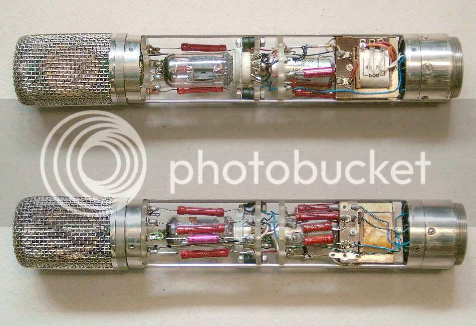
I have drawn this from the C12 schematic.

How does it look?

I have edited the connection of the 30W resistor. It should go straight from pin 3 to the capsule.

Is the capsule wired correctly?

Thanks in advance.

Hopefully we can put together a page spelling out fairly clearly how to clone one of these microphones
 

Attachments

  • c12 layout.jpg
    c12 layout.jpg
    149.5 KB · Views: 126
Here's the original schematic

Also,

are all the resistors 1W?

What should I use for the various caps? Polystyrene, mica, oil?
 

Attachments

  • AKG-c12.pdf
    41.3 KB · Views: 68
As for the PSU,

how about this
 

Attachments

  • universal_tube_mic_psu_rev_c.pdf
    250.6 KB · Views: 53
The resistors don't need to be 1W.    Since most of the resistors are extremely high R, they won't be passing much current & therefore won't be dissipating much power.  The only ones I would think of making 1W would be the 100k, but even with the full 120v across them they are only making 0.144W.

You can calculate the power dissipation using the following P=IV  or V^2/R  or I^2*R.
 
Rob,

does my C12 diagram look correct? Have I attached the capsule correctly?

thanks

Michael

Plus here's the pin layout of a 6072A
 

Attachments

  • 9a.gif
    9a.gif
    2.6 KB · Views: 18
The AKG C12 is highly documented on this site. Here is the pdf of the mic, power supply, and remote pattern selector after about 5 seconds of searching.

http://www.groupdiy.com/index.php?action=dlattach;topic=44737.0;attach=8315

Hope it helps.
 
the c12 is not well documented. this is why i started this thread

the link you posted is the original schematic. this is what i drew my first post from.

Got that bit. ;)

I need more than this.

Thanks anyway ;D

 
akgc12-inside.jpg

 
This is a good picture. From the recording hacks website.

Can anyone identify the parts placement?

I've tried with my layout but have failed slightly
 
As far as trying to nail the actual component layout of this particular mic, the mic isn't really proper mic design anymore. The ELA M 251 was designed (by AKG) around some of the shortcomings in the original C12. Specifically, the extra distance between the capsule and tube which increased noise.

The main thing you would really want to get right is the headbasket/capsule interaction. The chinese C12 copies (actually, the chinese mics are single-sided C24's) are built well, and crafting a headbasket to match the original C12, replacing the capsule, and upgrading the electronics (you can even keep the same PCB) would be a fairly simple way to get you a great mic. It will be up to you how much money you are willing to spend on the capsule/transformer/electronics, and how much time you're willing to spend on tweaking it to your liking to get an accurate clone.
 
Rob Flinn said:
The resistors don't need to be 1W.    Since most of the resistors are extremely high R, they won't be passing much current & therefore won't be dissipating much power.  The only ones I would think of making 1W would be the 100k, but even with the full 120v across them they are only making 0.144W.

You can calculate the power dissipation using the following P=IV  or V^2/R  or I^2*R.
Yes, but be careful. Some of the lower wattage resistors can break down at the high working voltages present in tube circuits.  So check out the Maximum Permissible Voltage too on the data sheet e.g. Vishay mrs25 is 350V 600mW versus Multicomp mf25 250V 250mW. You can also get high current surges at switch on as large PSU reservoir caps charge up. You should also be aware of what's going to happen in various fault situations. I tend to use flameproof versions for the high voltage power supply (R1 R2 R3 R4) e.g. Welwyn EMC2 2W fusible cement encapsulated metal film resistors just in case there's a short circuit. Or Vishay NFR25H They're only a few cents each. Or even Welwyn W23 10W ww ceramic. I'm personally also not so sure about VR1 in the HT PSU path either. Pots can go open circuit or be noisy. That's also the way it was in the original C12: 1K fixed value.

C12 schematic including PSU or here
 
FWIW the one in the pictures above is an early version, still with the big tranny. The earliest was a Hiller T14 and then came the Henry Radio V 2148 that is in the pictures.
AMI/TAB makes a good copy of the Hiller.

The latest (third) version is the much smaller T14/1, still made today, by Haufe.

akg%20c12%20transformer%20types.jpg
 
thanks guys,

has anyone got  a clear idea of how the capsule is connected?

I notice it has four wires. Are the two backplate wires connected together or do they have different paths as per the schematic?

thanks again

Michael


Latest posts

Back
Top