Console PSU keeps blowing diode bridge. What to do?

GroupDIY Audio Forum

Help Support GroupDIY Audio Forum:

This site may earn a commission from merchant affiliate links, including eBay, Amazon, and others.

Ilya

Well-known member
Joined
Feb 25, 2005
Messages
752
Location
Moscow
I've got a Euphonics CS console that started to act really funky lately.
There's a huge linear PSU with a bunch of 3A regulators in TO-3 cases (8 pos and 8 neg). They are fed from a single 50A bridge followed by some silly huge caps. Like 10000uF 70000uF per rail.

Sooo. All this developed a nasty habbit of making a fireworks once in a while. During the power up the 50A bridge dies with the fire and smoke show. This doesn't happen every time, not even every week, but once a month we get this fire show for sure.

Now, I wrote to smart guys at Euphonix and asked if they were aware of this behaviour. And the answer was: yes, we put in 60A bridge instead. Great. I've built up a custom bridge with 80A schottkies. You can't go wrong with 80A schottkies, can you?

It turned out you can. Today I witnessed the death of 2 diodes with smoke and fire during startup. The PSU was unloaded if this matters.

I've talked to all credible techs here who are still willing to do repairs of this console (frankly, just a couple of guys) and they all told me to f..k off. Politely. Nobody wanted to get their hands dirty with this.

One of them suggested inserting the 1 or 2 Ohm resistor right after the bridge and arrange a relay that would short it out after some time. This will decrease the inrush current to manageable.

I'm almost ready to implement this, but I wanted to ask smart guys here if there are any other ways of dealing with this problem? The misterious thing is that this problem developed over time. This leads me to conclusion that maybe something is wacky down the line. Don't know how to check this though.

And yes, leaving the desk turned on continuously is not an option.
 
I actually designed an old power amp using an even older tube power supply switch that allowed for turning on the heaters before main power. I used this on-on-off switch to allow for a series R at first turn on, and then shorted out the R after the initial surge.

There are dedicated surge suppressors that sit in series with the mains power, but these can wear out and waste power.

Today I might be tempted to do something with a solid state relay to short out the series R after the PS is up to voltage.

it might be easier to apply a solid state switch in series with the big reservoir caps inside the supply as that would be switching mostly DC so easier to control.

The problem is the surge when first powering up.

It might be possible to never completely turn off the PS so the caps stay partially charged, but not charged up high enough to draw much power.  But this isn't green...

JR


JohnRoberts said:
it might be easier to apply a solid state switch in series with the big reservoir caps inside the supply as that would be switching mostly DC so easier to control.

Do you mean the ss switch instead of mechanical relay?
There's like 25A of DC there. The IC should be capable of handling that reliably.
Can you point me in the direction of usable schematic - I'm not that good at designing stuff (although I can if absolutely needed).

Leaving the PSU even particialy energized is not an option unfortunately.
 
First of all using schottky diodes probably makes the things worse - at least at my experience.  They are more sensitive than normal diodes, especially against reverse voltage (you have to consider the peak AC-voltage).  Which voltage ratings do these diodes have ?

Second the trick with the resistors bypassed by a relay is very common, but I doubt 1 Ohm will do it.  Better use 10 ohms and short them after ~ 1 sec.  You can do this on the primary side too.  15 years ago I constructed such a unit (3-phase/16A for a big LED-display which was using toroid transformers).

Third semiconductor bypass is possible but again you have to consider the sensitivity of the device (to damage) and the heat produced.  Therefore I prefer relais.

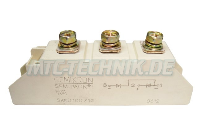
Fourth maybe you problems will be solved when you use correct components.  I would recommend, that you look for such diode modules like from semikron.  They are designed for rough environments:

1_semikron_dioden_module_SKKD100-12_semipack.jpg

 
analogguru said:
First of all using schottky diodes probably makes the things worse - at least at my experience.  They are more sensitive than normal diodes, especially against reverse voltage (you have to consider the peak AC-voltage).  Which voltage ratings do these diodes have ?

The diodes I used are Vishay VS-80CPQ150. They are rated at 150V, 80A. They should hold up to 1930A direct peak current which looks plenty to me, no?

analogguru said:
Second the trick with the resistors bypassed by a relay is very common, but I doubt 1 Ohm will do it.  Better use 10 ohms and short them after ~ 1 sec.  You can do this on the primary side too.  15 years ago I constructed such a unit (3-phase/16A for a big LED-display which was using toroid transformers).

Ok, I'll do some calcs and find out what is better. 10R looks like a more viable choice and dissipation power will be 10 times less then with 1R.

analogguru said:
Fourth maybe you problems will be solved when you use correct components.  I would recommend, that you look for such diode modules like from semikron.  They are designed for rough environments.

If I find these locally, would you still suggest implementing relay circuit or can I live without it?
Also, there're 2 diodes in 1 package. Do I have to get just 2 of those Semikron modules, or should I go for 4?
 
Adding the inrush resistor on the primary side of power transformer reduces the inrush current by the transformer turns ratio.

A solid state relay to short out say a 10 ohm power resistor should work. I used a 10W but 5W may be OK.  A solid state relay (or real relay) that shunts the resistor after power comes up, with the coil or trigger powered by a delayed output from the power supply should work. I used a real relay in my early 1970's power amp. In fact I used the same control signal to turn on relays that connected the speakers for quiet turn on/off.

Not complicated but be careful with mains voltage wiring, and isolation between mains and regulated power supply side.

JR
 
JohnRoberts said:
Not complicated but be careful with mains voltage wiring, and isolation between mains and regulated power supply side.

Yeah, that's why I'm more inclined to make this a part of DC circuit instead. I've got the 30A 120V stepdown already :)
 
The quickest easiest way to do this is with a large bulb as your inrush resistor, and an a.c. relay.
Wire the bulb in series with the primary. Put the relay after the lamp in parallel. At switchon the lamp will limit the inrush, the voltage across the relay will rise, and the relay finally shorts out the lamp.
Use a 200 to 500 watt bulb. The unit can be wired as an external addon, with appropriate plug and socket.
This is good for testing big power amps too, the lamp turns on if you have a big short.
 
something similar happened on one of our consoles
the heater rail kept blowing the bridge


turned out the reservoir cap had gone funky
 
Ilya said:
JohnRoberts said:
Not complicated but be careful with mains voltage wiring, and isolation between mains and regulated power supply side.

Yeah, that's why I'm more inclined to make this a part of DC circuit instead. I've got the 30A 120V stepdown already :)

Understood... just saying 30A secondary is probably <10A primary.

Simplest low voltage approach is putting some high current TRIACs in series with ground leads of the reservoir caps. This requires two resistors and two triacs but you should still be able to drive from a common gate delayed gate voltage.

Having never done this on the secondary side I may be overlooking something.

I still like the thought of doing this on the primary side because of simplicity and lower current.  I recently did a little DIY project using a small optical gate triac, to fire a high current triac. So I had all the isolation from mains voltage to do this safely, and I could turn the high current on and off with few mA into a LED on the input side of the opto triac.

KISS.

JR

jplebre said:
something similar happened on one of our consoles
the heater rail kept blowing the bridge


turned out the reservoir cap had gone funky
I have seen issues with shorted diodes drawing huge current feeding AC into reservoir caps, and similarly shorted caps drawing huge current from diode bridges. Generally such faults will take out the product mains fuse, sometimes UL adds an extra internal fuse if their testing reveals that such faults don't pop the product fuse.   

JR
 
I have seen issues with shorted diodes drawing huge current feeding AC into reservoir caps, and similarly shorted caps drawing huge current from diode bridges. Generally such faults will take out the product mains fuse, sometimes UL adds an extra internal fuse if their testing reveals that such faults don't pop the product fuse.   
Yes indeed. the heater rail internal fuse blew. Which also killed all the LED, switching and fans
 
A hard way but more elegant and stable IMHO is a triac in the primary with slow turn on control and a relay activated when caps get fully charged, when the relay bypass the triac also connects the output to the console. Maybe I'm overthinking it, but I guess this way you eliminate all the risk, a pot with a switch controling the triac and the relay may be an easy way of doing this and can be completley out the PSU if it's not a problem to the desk get the voltage in the turn on time.

JS
 
Again: forget about using a triac, (DC: thyristor) or solid state relais (= triac inside) at this (relative) high current application.  Vtm (peak on-state voltage) of a usable triac is about 1,5V.

1,5V x 30A = 45W

45W heat per triac/thyristor you produce which you have to get rid off with a not so small heatsink.  With a relais/contactor: 0 W

Why do you think that thyristor-converters have a big heatsink with an attached fan:

$(KGrHqQOKkYE2Kv+rgBNBNynsu6N7g~~_12.JPG
10258_0.JPG


And there are even more reasons..... but I don´t have the time for electronic lectures now.

Simply don´t do it this way and you will have less problems.
 
jplebre said:
something similar happened on one of our consoles
the heater rail kept blowing the bridge


turned out the reservoir cap had gone funky

This was my first thought when reading the initial post - it's not the rectifier that is causing the problem, it's the caps.  If the PSU worked for some period of time before the trouble started then something has changed.  If changing the burned components doesn't get you back to where you started then those were not the components that caused the problem.  Test the caps, regulators, and any other parts downstream from the rectifiers.  Chances are good that something has gone south.
 
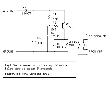
Ok. Triacs, ss switches and other stuff is not something I'm willing to use because of power dissipation and relative complexness. I've found the following relay delay circuit:
ampdelay.gif

It's rated for ~24VAC and relay coil should have more than 300R resistance. For now, I have ~21VAC available, so I'll have to use 12V relay instead. Do I have to adjust any components values? I guess I have to put a series R with relay coil.

mjrippe said:
Test the caps, regulators, and any other parts downstream from the rectifiers.  Chances are good that something has gone south.

How would you test a 35000uF cap? I'm pretty sure the regs down the line are ok.
 
How would you test a 35000uF cap? I'm pretty sure the regs down the line are ok.

test the resistance between the leads. make sure its discharged first though.
You may have to remove any big dissipation resistors that may be attached first
 
jplebre said:
test the resistance between the leads. make sure its discharged first though.
You may have to remove any big dissipation resistors that may be attached first

Ok, will do. I've just dug out the schemo of some part of the psu, and there're actually 1K resistors mentioned. I wonder if one of them failed...
 

Attachments

  • caps.JPG
    caps.JPG
    19.6 KB · Views: 18
Ilya said:
jplebre said:
test the resistance between the leads. make sure its discharged first though.
You may have to remove any big dissipation resistors that may be attached first

Ok, will do. I've just dug out the schemo of some part of the psu, and there're actually 1K resistors mentioned. I wonder if one of them failed...
Very unlikely... there would be visible evidence of the resistor overheating.

JR
 
Forget the diodes and resistors. They should practically last forever. I would have a look at those caps in isolation. They are the most failure-prone parts in there and it seems this PSU is quite demanding for them.
 
Sorry if I understated the degree of difficulty using a triac or solid state relay. Such a relay sized for the current would most likely have a heatsink designed into the package. Note: it isn't 30A at the primary side but it would generate heat.

21V is close enough to 24V that I wonder if a 24V relay might work, but that is NOT good design practice and leaves no margin for low line. A 12V relay with dropping resistor will work. The dropping resistor may need to dissipate a few watts. Since a 12V relay, all else equal, will draw twice the coil current you may need to scale the circuit for more transistor base current, etc. You don't need much delay, depending on size of resistor in series with mains.

For more of an exotic mental exercise, a technique called synchronous rectification (I think) used in high current low voltage supplies replaces the diodes with power switching devices to eliminate the waste heat from the forward diode drop. A variable synchronous rectification could slowly ramp up the voltage sent to the capacitors.  OK I'm done now, don't seriously try that (its probably hard to apply at 24v level.).  ;D

At some point we should take a step back and ponder why we are essentially redesigning a product years after it has been put into service. Were these PS always a hot mess, or has something degraded? In my experience caps fail or they don't. If you suspect the caps, such faults will usually reveal in a visual inspection. Look for swelling or leakage. Sometimes if they are left powered off for very long periods of time, they may need to be re-formed in, but I'm talking sitting for years not days.   


If installing new/old caps it might be a good idea to bring PS up slowly with a variac. Perhaps a useful practice for any product using very large caps.

JR


Latest posts

Back
Top