Console PSU keeps blowing diode bridge. What to do?

GroupDIY Audio Forum

Help Support GroupDIY Audio Forum:

This site may earn a commission from merchant affiliate links, including eBay, Amazon, and others.
Ilya said:
I'll check with the scope, but I'm really not so willing to turn this thing on without any protection. Each failure is expensive and takes quite a lot of time to fix. Besides, I hate soldering 8awg wires ;)

Will it be as informative if I check the voltage with slow start engaged?
Sure... for general info.  Fault caused by simple turn on does not make sense if nothing has changed.

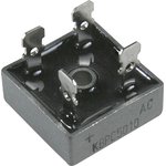
BTW what is PIV spec on diode bridge... ? Some high current bridges are not high voltage, while that should not fail preferentially at turn on, unless they fail every time they turn on.  8)
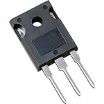
I believe that shorted diodes are a legacy from the last failure, when 3 regs went to the better place. I think that these diodes were right there with those regs.

Still a mystery to me.

JR
 
First replacement of the bridge has been done by some tech. He told me that the part has been replaced earlier so I have no idea what original part was. The replacement bridge was 50A KBPC type like this one:

DOC000213731.jpg


This was a chineese part, it states 1200V PIV.

Now the bridge is replaced with 4 shottkies Vishay VS-80CPQ150 like these:

DOC000290609.jpg


Those are dual diodes, I've paralleled them.
 
As this happens at the "On" inrush surge point ,What about an  HV insulation test on the that large transformer , Pri to Secondary ,
And to lamination's or chassis earth
In Disconnected and isolated mode of course....
Seen a similar fault like this before.....pri sec short at switch on ...due to a flash over.


That seem like more than enough PIV.

I have seen funny behavior with large EI transformers then turned on away from zero crossings in mains signal but that seems completely unrelated to your fault condition.

Another outside the box idea is create a LC filter which could reduce the peak current, but I can't start to suggest a practical inductor and keep returning to the why now?

JR
 
Without a schematic I am a bit lost, but I was assuming that they acted in a ganged fashion with outputs connected in some way to form a larger regulator (perhaps isolated so they don't fight). 

I have never worked on a PSU with this much Umph....

But if a member of the gang of regulators is misbehaving, whether they are before or after the big caps, that could increase the current drain AND duration.

b
 
bruce0 said:
Without a schematic I am a bit lost, but I was assuming that they acted in a ganged fashion with outputs connected in some way to form a larger regulator (perhaps isolated so they don't fight). 

No, they are not isolated. I've attached the schematic of all parts.

[EDIT]
The fried diodes were the ones marked D1 on neg reg circuit
 

Attachments

  • eu_PSU.JPG
    eu_PSU.JPG
    176.1 KB · Views: 31
Using a 100-220uF (35V) cap as C2 in both the negative and positive regulator circuits (marked as "not fitted" in the schematic) would make a poor mans slow start up. That would be one way to significantly cut down the inrush current blast.
 
Kingston said:
Using a 100-220uF (35V) cap as C2 in both the negative and positive regulator circuits (marked as "not fitted" in the schematic) would make a poor mans slow start up. That would be one way to significantly cut down the inrush current blast.

Actually, "not fitted" is regarding the link between pins 3 and 4 of the reg. C2 are tantalums, 2.2uF with small footprint. I'll see if it's possible to fit 100uF there.

[EDIT]
To replace those caps I'd have to desolder those regs again. What a pain in the butt... Need to make sure the PCB will survive this.
 
also remember heat is a serious concern for electrolytics even if they fit so this start up trick might not be viable long term option. Modern tantalums will take more serious beating.
 
Ilya said:
Now the bridge is replaced with 4 shottkies Vishay VS-80CPQ150 like these:

DOC000290609.jpg


Those are dual diodes, I've paralleled them.

you used four of these? that makes no sense - diodes do generally not like to be paralleled as far as I know... the are meant to form 1/2 of your rectifier bridge.... now to Schottky diodes, they are good at reducing losses, but that seems not to be the main point here. on the other side they have far smaller max reverse voltage if i am not mistaken.

why your supply is faulting in the first place is unknown to me but you might try to put a regular silicon bridge rect back into there. add proper cooling, as these do get hot - 30A at 0.7V are 21W per diode in that package. two conducting at the same time equals roughly 40W at 30A. maybe less on average, but sure enough this is a high power application.

do you have 3 phase power over there? there is an elegant solution with three phase power supply for that kind of problems, mostly cutting down the recharging interval for the caps to 1/3 of normal that you could consider....

cheers,

michael
 
audiomixer said:
you used four of these? that makes no sense - diodes do generally not like to be paralleled as far as I know... the are meant to form 1/2 of your rectifier bridge.... now to Schottky diodes, they are good at reducing losses, but that seems not to be the main point here. on the other side they have far smaller max reverse voltage if i am not mistaken.

All schottkies that are available right away locally are packages with common cathode, not serial. You can't form a bridge with this configuration. I've researched paralleling diodes, and since they are on the same chip, it's safe to do so.

audiomixer said:
you might try to put a regular silicon bridge rect back into there. add proper cooling, as these do get hot - 30A at 0.7V are 21W per diode in that package.

There's a huge heatsink with a fan. Nothing can be added to aid cooling. Startup problem has nothing to do with cooling, I believe.

audiomixer said:
do you have 3 phase power over there? there is an elegant solution with three phase power supply for that kind of problems, mostly cutting down the recharging interval for the caps to 1/3 of normal that you could consider....

In theory it may be possible to bring 3 phase power there. But this would require PSU redesign and toroid trafo replacement, I guess. This solution is too expensive to consider.
 
Newark/Element 14 has come caps in stock in the UK that might work for you.  They are EPCOS 33000uf @ 40v.  Rated for 105ºC.  I know this is a bit lower capacitance, but they are within 10% and cost $25 instead of $70.
 
bruce0 said:
...But if a member of the gang of regulators is misbehaving, whether they are before or after the big caps, that could increase the current drain AND duration.

Hello,
I was also thinking about the role of the regulators in this inrush current problem since you said that three of the LT1033CK negative regulators died and took out their protection diodes.

By chance, have you checked the capacitance value and  ESR of the regulator's input and output compensation capacitors (C1 and C3)? Older tantalum caps are notorious for being unreliable.

According to the LT1033CK datasheet:
"...an output capacitor, C3 is required to provide proper frequency compensation of the regulator feedback loop. A 2uF or larger solid tantalum capacitor is generally sufficient for this purpose. IF the 1MHz impedance of the capacitor is 1 ohm or less."

Plus, the LM338CK's datasheet also mentions the need for a low impedance tantalum capacitor (C1) on the LM338's INPUT pin for stability. The tantalum capacitors must have an actual minimum value of 1uF.

Maybe some of your regulator's tantalum bypass caps are no longer close to 2.2uF or they may have developed a high ESR value, and some of the regulators are briefly oscillating at startup. I see on the datasheet that these regulators can pass a 12 amp current transient. At least you could test the ESR value of all of the tantalum capacitors in circuit. I've seen this type of brief startup regulator oscillation in a piece of gear I was working on years ago. The output ripple looked really bad on my oscilloscope too.

Just some food for thought.

Regards,
Frank
 
A broken piece of mica or more likley the insulating sholder washers could cause this, if voltage regulators are mounted to the same heatsink. Ohming it out for a short between regulator case and heatsink could exclude/manifest this.
 
fpliuzzi said:
By chance, have you checked the capacitance value and  ESR of the regulator's input and output compensation capacitors (C1 and C3)? Older tantalum caps are notorious for being unreliable.

Unfortunately I don't have an ESR meter. Maybe it's time to get one. I can check capacitance with the DMM though. Will see what it shows.

mjrippe said:
Newark/Element 14 has come caps in stock in the UK that might work for you.  They are EPCOS 33000uf @ 40v.  Rated for 105ºC.  I know this is a bit lower capacitance, but they are within 10% and cost $25 instead of $70.

Thanks for this. There're actually some fine caps rated for 10000hrs @ 85C which may be even better than 3000hrs @ 105C
 
I feel your pain!

I agree with not paralleling diodes, at these currents it is too easy for one diode of the pair ending up doing all the work.
I wonder if your thermal bonding / cooling of the diode bridge is insufficient. When the PSU is up and running with the console attached the diodes / bridge is getting hot and stressed such that on a next turn on, with all the planets aligned they throw in the towel.
I'd think it is unlikely that there are faults in the "small" caps, diodes etc around the reg sections as with the amount of power available any shorts would be very visible..smoke, melting metal etc. I've seen very high power PSU that have developed shorts within the mica washers and metal was vapourised.
Consider making a bridge from stud mount diodes. With lots of heatsinking to ensure don't run hot
 
squib said:
I agree with not paralleling diodes, at these currents it is too easy for one diode of the pair ending up doing all the work.

Not just these currents, but any currents, any diodes. Two diodes in parallel is basically a single diode from stability and performance point of view. When one fails because of problems elsewhere in the circuit, so will the other. But you paid for two.

Don't confuse them with resistors.
 
Thanks for comments, gents.
I'll replace the diodes with stud mounted ones (or just go buy those semikrons) when they fail.

I've found the cause of failure. It turned out that the heatshrink tubing on the positive rail eyelet developed a hole with the metal poking through. And this hole was right over the grounded metal plate. So every now and then this stuff shorted and took the bridge to the better place.

It's still a mistery to my how and why all the pos regs survived, yet 3 of neg regs went south together with protecting diodes.

Anyway, I've checked all the regs output with a scope and they looked fine. I've inspected the startup process on both rails and it looked good to me as well. Nonetheless, the slow start relay is in place and works as it should. Just in case, you know :)

Will see how lon this stuff will live.

[EDIT]
Definitely need to get a ESR meter. This may be a very useful tool.
 
Good job... It's always something.

You can perform some ESR tests with other bench equipment.

I'm glad you found it I was almost running out of ideas.  ;D (One I didn't mention yet was to alternately disconnect pairs of capacitors to see is they all act the same. )

JR
 
This thread made me look into capacitance and ESR measurement with lab equipment. seems you can measure both with a scope... who knew (not - do not reply ;-))

glad you found a sound explanation!

cheers,

Michael
 
Back
Top