TwinLineAmp Opto Compressor TLA2A

GroupDIY Audio Forum

Help Support GroupDIY Audio Forum:

This site may earn a commission from merchant affiliate links, including eBay, Amazon, and others.

ruffrecords

Well-known member
Joined
Nov 10, 2006
Messages
17,075
Location
Norfolk - UK
I have been asked many times if I am going to come up with a tube compressor design.  I always planned to but never got round to it what with designing various EQs, mixers and so on. Then recently I was approached by a group member who thought he would like to use the Twin Line Amp from the EZTubeMixer project as the basis of an opto compressor like the LA2A. This was very much what I was thinking so I helped him out and as far as I know he's working away on it right now. So I thought it was about time to put pen to paper to sketch out the basic idea. There's a lot of detail to work out but I know the principle is sound having built something similar for a client at the end of last year.

blockdiascaled.jpg


Referring to the the above block diagram, the signal passes through a 10K:10K transformer mounted on the TwinLineAmp (TLA) board then through a pot divider consisting of R1, R2 and the opto cell. The pot divider output goes via VR2 to one of the TLA amplifiers to the output. VR1 is the gain make up control and the intention of R3 is to set the zero position of VR1 to overall unity gain. S1 shorts out R2 to change from compression to limiting exactly as in the LA2A.

The side chain signal is taken from the junction of R1 and R2 to VR2 which is the threshold control. This sets the amount of compression applied to the signal. The output of VR2 is amplified by the second TLA amplifier and passes via C1 and R4 to the LED in the opto cell. A second LED is wired in the opposite polarity across the opto LED. This is necessary to prevent C1 and the opto LED acting as a simple charge pump. This second LED may or may not provide a useful indication of compression. R1 sets the LED current and may need to be altered depending on the chosen opto.

Gain reduction is roughly proportional to current through the LED so the gain reduction meter GR is set up to measure this current with VR3 setting the gain. With this set up there is no need for a meter zero adjustment.

I am fairly opto agnostic but in this topology the compression ratio, attack and decay times are determined largely by the opto so you need to think about the values you need. Also, the max and min resistance varies with opto type which affects the values of R1, R2, VR1 and VR2.

There is plenty of room on the TLA PCB to mount the opto and its associated components where the second input transformer would have been.

There are various enhancements you can consider such as using a pair of optos with their LEDs connected back to back so both halves of the signal are taken into account, or stereo linking.

Through this thread I am happy to support anyone who decides to build an opto compressor based on the TLA.

Comments, suggestion and questions are welcomed.

Cheers

Ian
 

Attachments

  • blockdiascaled.jpg
    blockdiascaled.jpg
    213.7 KB
I pretty much just need to build the power supply to get the amp card up and running, get hold of an input transformer and figure out the correct values for R1 and R2 and I'm ready to test my first 'TLA2A' :)
I have a VTL5C2 and VTL5C4, although which would sound best I couldn't say...
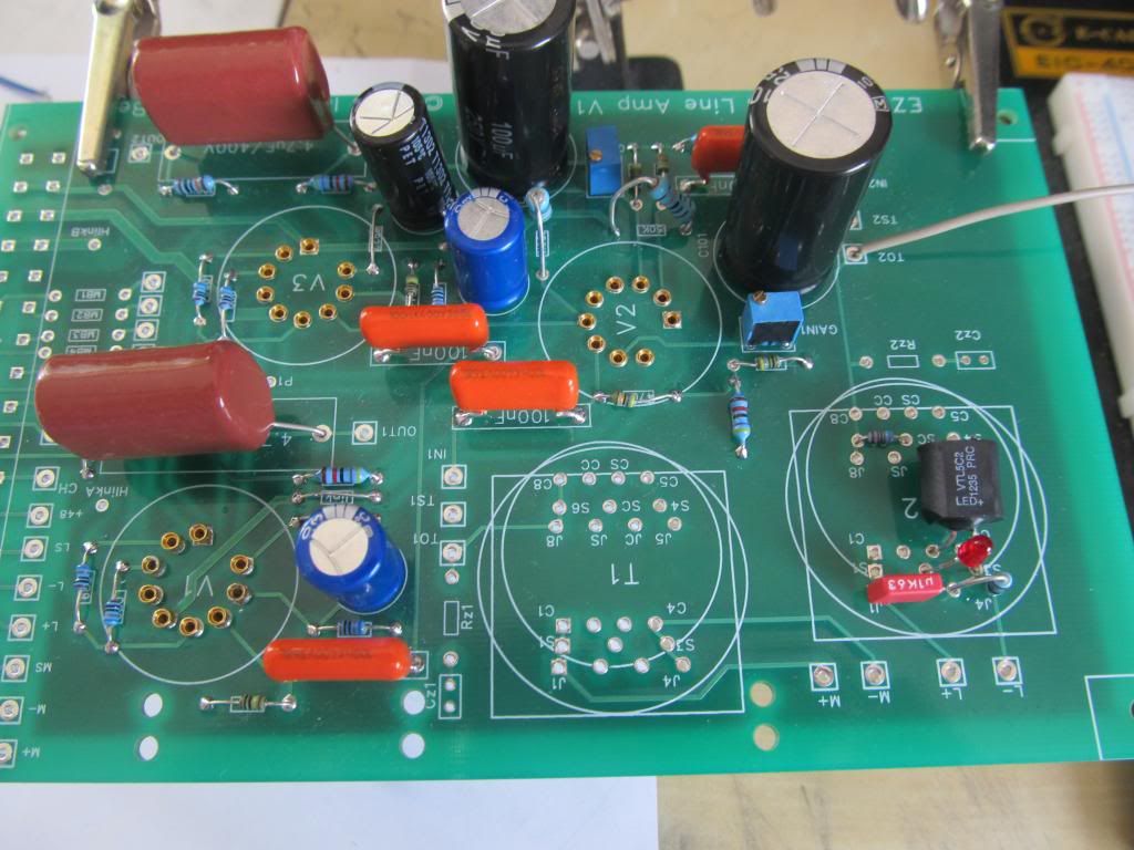
(the capacitor in this picture isn't the right value (I think 4u7 is correct) but is just there for show...)


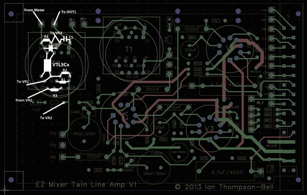
I've tried to arrange the parts on the PCB, using the free traces where possible. I think I have a layout where all components (except pots and meter) can be mounted on the PCB. Here is a quick layout, please excuse the bad paint-job! It may be that it is a bit difficult to connect a switch across R2, but you could mount R1 from pad C8 to pad CC (moving the right leg of R3 to pad CS) ad that would leave the SC pad and the pad directly to the right free - but you'd need a jumper from SC to JS.
Does this layout look like it will work?
 
BTW, This twin line amp card is just brilliant (along with the idea of using the readily available eurocard format to simplify mechanics etc). I have plans to build compressors, EQ's, a nice headphone amp and a couple of preamps all using this one card. Reading all about the eurocard format has also inspired me to start breadboarding my own eurocard designs :)

I just hope that you'll be providing the PCB's for long enough for me to buy all the ones I plan I'll need!!!
 
ramshackles said:
BTW, This twin line amp card is just brilliant (along with the idea of using the readily available eurocard format to simplify mechanics etc). I have plans to build compressors, EQ's, a nice headphone amp and a couple of preamps all using this one card. Reading all about the eurocard format has also inspired me to start breadboarding my own eurocard designs :)

I just hope that you'll be providing the PCB's for long enough for me to buy all the ones I plan I'll need!!!

That's exactly what I was trying to do when I came up with the TLA. Its a nice compact versatile building block. Saves me a huge amount of design and PCB layout time. I think I need to update the TLA config document to add its ability to be come a compressor. I also discovered recently that it makes a really good tube TransAmp which is perfect for virtual earth mixing so I need to add that in too.

I recently received a new batch of PCBs so there's little chance of running out just yet. I plan to use them in most of my own builds so I expect to have them around for a few years yet.

Cheers

Ian
 
ramshackles said:
I pretty much just need to build the power supply to get the amp card up and running, get hold of an input transformer and figure out the correct values for R1 and R2 and I'm ready to test my first 'TLA2A' :)
I have a VTL5C2 and VTL5C4, although which would sound best I couldn't say...
(the capacitor in this picture isn't the right value (I think 4u7 is correct) but is just there for show...)
I've tried to arrange the parts on the PCB, using the free traces where possible. I think I have a layout where all components (except pots and meter) can be mounted on the PCB. Here is a quick layout, please excuse the bad paint-job! It may be that it is a bit difficult to connect a switch across R2, but you could mount R1 from pad C8 to pad CC (moving the right leg of R3 to pad CS) ad that would leave the SC pad and the pad directly to the right free - but you'd need a jumper from SC to JS.
Does this layout look like it will work?

The layout looks pretty good.Just a couple of points. I made an error in the block diagram of the first post. I got the extra LED the wrong way round. I have corrected it now and the diagram in the first post is now correct.

I assume you are coming in thru M1 and M- so you need a link from TO1 to R1. You also need a link from VR2 slider to IN2 and from VR1 slider to IN1 (I assume you omitted these for clarity).

You don't need C1 - it's already there - it's the 4.7uF connected to OUT1 on the PCB.

I am not quite sure how the layout works with VR2 and the meter - check the PCB underside because most of the pins in the centre of that area are unconnected so you may need to add some links. Conversely, at the bottom of T2, all the pins are connected directly to 0V except for J8, S6 and C8 which are connected together and to TO2.

Cheers

Ian
 
Hi Ian,

I have nothing but admiration for your work here and have learned much so please take this in the spirit it was intended.  Doesn't using a tube stage to drive an LED seem a little wasteful?  A simple layout could allow for an opamp LED driver stage which would be cheaper, lower heat and have less PSU demands for those that want to put more than one compressor in a chassis.

My second thought is that I've used enough LED/Vactrol based compressors to know that without a smart sidechain the time constants are not very useful.  I'm currently using one two of the very best Opto comps in my mastering room, one of which has a mode feeding the LED directly as you have.  I have yet to find a use for it.

The Twin Line Amp is a wonderful thing and building an opto compressor from it is a natural step.  I think it's worth the effort to either use a T4B style opto to get nice audio behavior or add a sidechain circuit that is a little more complex.

As always I find your project fascinating.

Cheers,
Ruairi
 
ruffrecords said:
The layout looks pretty good.Just a couple of points. I made an error in the block diagram of the first post. I got the extra LED the wrong way round. I have corrected it now and the diagram in the first post is now correct.

I assume you are coming in thru M1 and M- so you need a link from TO1 to R1. You also need a link from VR2 slider to IN2 and from VR1 slider to IN1 (I assume you omitted these for clarity).

You don't need C1 - it's already there - it's the 4.7uF connected to OUT1 on the PCB.

I am not quite sure how the layout works with VR2 and the meter - check the PCB underside because most of the pins in the centre of that area are unconnected so you may need to add some links. Conversely, at the bottom of T2, all the pins are connected directly to 0V except for J8, S6 and C8 which are connected together and to TO2.

Cheers

Ian

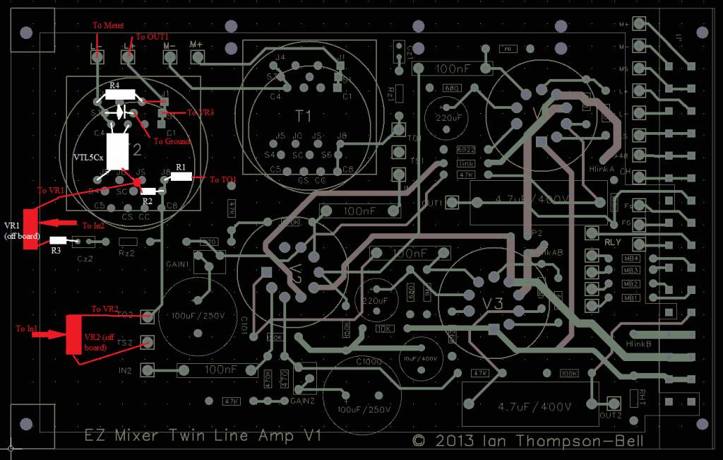
Ahh right, I missed the ground connections. I had missed of some wire links for clarity, but it is easier to draw it with everything in. So, the white markings is stuff that is mounted on the board, the red is stuff that is mounted off board, or wire links.


ruairioflaherty said:
Hi Ian,

I have nothing but admiration for your work here and have learned much so please take this in the spirit it was intended.  Doesn't using a tube stage to drive an LED seem a little wasteful?  A simple layout could allow for an opamp LED driver stage which would be cheaper, lower heat and have less PSU demands for those that want to put more than one compressor in a chassis.


What you say is true.It would be quite straight forward to add a little semiconductor side chain board with whatever signal conditioning was necessary to provide any type of performance from a Vactrol and make a nice stereo compressor and of course I have no objection to that whatsoever. However, I am a tube guy at heart and my personal preference is for the avoidance of semiconductors. Apart from power supplies and the Vactrol I don't use them at all.

My second thought is that I've used enough LED/Vactrol based compressors to know that without a smart sidechain the time constants are not very useful.  I'm currently using one two of the very best Opto comps in my mastering room, one of which has a mode feeding the LED directly as you have.  I have yet to find a use for it.

Here I must remain mute because I have no wish to offend anyone for whom mastering is a profession. Suffice to say, I agree this design does not meet the needs of today's mastering engineer.

The Twin Line Amp is a wonderful thing and building an opto compressor from it is a natural step.  I think it's worth the effort to either use a T4B style opto to get nice audio behaviour or add a sidechain circuit that is a little more complex.

As always I find your project fascinating.

Cheers,
Ruairi

Thanks for the kind words Ruari. A couple of years ago I did a lot of work on a more comprehensive design with a much more complex side chain with its own rectifiers and adjustable attack/decay/ratio controls. The idea was to use a very fast acting Vactrol and determine attack/decay etc. entirely in the side chain. I had to put that to one side to pursue other projects and, as I said in the first post, I have never got round to finishing it. The TLA version has  been in the back of my mind as an easy first step for several months but it only crystallised a few weeks ago when ramshackle contacted me to ask if it was possible. I thought if one group member was interested in the idea then others might also be, hence this thread.

The more ambitious version is still waiting to be picked up. I confess I am semiconductor averse and I would rather have a tube gain element than a Vactrol. But that's the big problem; for tubes it's basically vari-mu or nothing which tends to lead to a lot of extra transformers and balancing pots. Yes, there's a number of quirky circuits about but they all fall short one way or another.

So many projects, so little time.

Cheers

Ian
 
I have been lookig at some other aspects of this project. One thing that had bugged me for a while is that the opto LED only works on one half cycle of the audio waveform. You sometimes get asymmetrical waveforms so with only looking at one of them you could get over or under compression.  Most pro compressors use full wave rectification so both halves af the waveform are taken into account so I have devised a circuit to do this:

bridgedrivescaled.jpeg


The four 1N4148 diodes form the required bridge and I have moved R4 and the gain reduction meter to the other side of it so they are ground referenced. If have done some simulations of this circuit to verify that it should work but I have not built it. The diodes do raise the threshold by two diode drops but there's enough output swing in the TLA to overcome that. The sims indicate that, with R4 set to 1K, just under +9dBV at the output is required for 1mA LED current and +20dBV is required for 10mA LED current.

Lastly a quick word about Vactrol types and R1, R2. In this compressor,as in all LA2A lookalikes, attack and decay time, program level dependent performance and the ratio are entirely dictated by the chosen Vactrol. These factors also vary with drive level and with the length of time they are operated. Furthermore, the attack and decay times given in the datasheets only apply at a minimum current of 10mA which is probably the maximum current they will ever see in this design. So the spec sheets are at best only a guide to the figures you will actually obtain. Having said that, Vactrols tends to fall into broad categories so we can make some generalisations about the most common ones.

VTL5C1. attack 2.5mS, decay 35mS. Resistance, approx 20K at 1mA and 600R at 10mA. Very wide dynamic range. Should make a relatively fast compressor. Try R1 = 100K

VTL5C2. attack 3.5mS, decay 500mS. Resistance, approx 5K5 at 1mA and 800R at 10mA. Fair dynamic range. Slow decay so probably better as a limiter. Try R1 = 68K

VTL5C3. attack 2.5mS, decay 35mS. Resistance, approx 30K at 1mA and 5R at 10mA. Good dynamic range. I have used these and they do make a relatively fast compressor. Try R1 = 100K. A 20dB gain reduction is possible.

VTL5C4. attack 6mS, decay 1.5secs. Resistance, approx 1K2 at 1mA and 125R at 10mA. Fair dynamic range. Very slow decay so probably better as a limiter. Try R1 = 22K

Bear in mind that in all cases the threshold is determined by the forward voltage of the opto LED and any other diodes in series with it. So, in the simple version you need about 1.5V peak or 1.1V rms or about +2.7dBu at the LED before any gain reduction occurs. If you set the side chain TLA gain to 30dB then your lowest threshold will be about -27dBu. If you use the bridge, the threshold at the LED rises to about 2.8V peak or 2V rms or about 8dBu so the lowest threshold rises to -22dBu.

Cheers

Ian

 
ramshackles said:
Ahh right, I missed the ground connections. I had missed of some wire links for clarity, but it is easier to draw it with everything in. So, the white markings is stuff that is mounted on the board, the red is stuff that is mounted off board, or wire links.

That looks OK to me.

Cheers

Ian
 
Hi
What kind of values for the pots?
How would you normally work out the value of pots/faders in such a configuration? (i.e. across the inputs of amps) Is it just about the amount of attenuation you want?
 
ramshackles said:
Hi
What kind of values for the pots?
How would you normally work out the value of pots/faders in such a configuration? (i.e. across the inputs of amps) Is it just about the amount of attenuation you want?

It basically depends on the value of R1. You need to arrange it so that the two pots together do not cause a lot of attenuation when the opto is not operating. A reasonable start is to arrange them so their combined resistance is at least equal to R1. So if you have R1 = 68K then using 220K or 250K pots would be OK. You could probably get away with 100K pots.

Cheers

Ian
 
I have been thinking about Ruairi O'Flaherty's question " Doesn't using a tube stage to drive an LED seem a little wasteful?". It made me remember the first version of a compressor I did for a client which was based around standard 6L6 single ended output amp which had 20 something dB of gain. I used one of the speaker windings and drove a Vactrol LED straight from it via a 1K resistor. The opto resistor was set up as a pot divider at the amp's input feeding the volume control. It worked reasonably well. There was only one control, the volume pot, and this set both the amount of compression and the gain make up so all you had to do was turn it up until you got the compression you wanted.

It occurred to me that you could probably do something similar with the TLA and make two compressors from the card. It then dawned on me that the VTB2291 output transformer I use has two secondaries. One could be used for the signal output and the other could be used to drive the Vactrol. Nothing special about that but then I realised if I connected the Vactrol driving secondaries in series I had a mono signal so it could be made into a stereo compressor. Attached is a rough schematic showing how it might work. Each TLA is set for 40dB of gain to allow for the 12dB loss in the output transformer and, say, 3dB loss in the opto attenuator with no signal giving an input threshold of around -25dBu.

I have not built this but I am awfully tempted.

Cheers

Ian
 

Attachments

  • TLAstereocompscaled.jpeg
    TLAstereocompscaled.jpeg
    148.5 KB
Stereo compressor from one card, sounds good :). Maybe after I've built the mono one....

About it being wasteful using a tube stage for the sidechain.....although it is not directly in the signal path, won't the differences between a tube amp and e.g. an IC amp cause differences in the way the vactrol responds and therefore the compression?
 
I guess there will be some difference because the tube is really a voltage source device and the LED is really a current sink. In my design the 1K resistor acts as a very crude voltage to current converter. ICs are much better at dumping current. Whether any of that translates into an audible difference is anyone's guess.

By the way, I just tried out DigiKey's SchemeIt web based schematic capture app. Attached is a neat version of the sketch I posted earlier.

Cheers

Ian
 

Attachments

  • EZcomp.pdf
    37.3 KB
ruffrecords said:
I have been thinking about Ruairi O'Flaherty's question " Doesn't using a tube stage to drive an LED seem a little wasteful?".

It's to your credit that you took my suggestions in the spirit they were in intended, thank you.  In your usual style you have put a new twist on an old thing, I'm fascinated by where you'll take this latest idea.

Cheers,
Ruairi
 
ruffrecords said:
By the way, I just tried out DigiKey's SchemeIt web based schematic capture app. Attached is a neat version of the sketch I posted earlier.

Cheers

Ian

I am trying to understand the schematics and as usual they are making little sense to me... to start with, are there some parts from the original missing in the digikey version? Like R1 and VR1?

sorry for asking the probably obvious...

Erik
 
ahhh that makes sense.. by leaving stuff out, it turns stereo ;-)
Seriously, I was referring to reply #12, that one is stereo too right?
 
erikb1971 said:
I am trying to understand the schematics and as usual they are making little sense to me... to start with, are there some parts from the original missing in the digikey version? Like R1 and VR1?

sorry for asking the probably obvious...

Erik

R1 is still there but it is called R4 now; that's just how the automatic component numbering system works in SchemeIt. I have not yet worked out how to renumber them.

VR1 is indeed missing because I am not sure it is necessary and it might even confuse the user. Without VR1, if you set the TLA gain to 40dB, then below the threshold there is about 24dB of gain available. The other factor to consider is that  the threshold is close to +1.6dBu at the output and when the output reaches about +9dBu you close to 24dB of gain reduction with R2 (which was VR2) turned fully up.

So, imagine the output is at +9dBu and VR2 is fully up. There will be 24dB of gain reduction and 24dB of gain, so the input must also be at+9dBU. This is the lowest input level at which you can get full gain reduction. If you put back VR1 then this would only serve to make you need an even higher input level to get full gain reduction so I thought we probably don't need it.

I am starting to confuse my self now because if we set VR2 to 24dB loss we have 0dB overall gain. If the output is +9dBu then the output of the opto must be +9dBu which means its input needs to be +33dBu which is just plain silly. However, this is because we have now raised the threshold to about 0dBu so at normal levels we will only get a small amount of gain reduction.

I need to think some more about this.

Cheers

Ian
 

Latest posts

Back
Top