TwinLineAmp Opto Compressor TLA2A

GroupDIY Audio Forum

Help Support GroupDIY Audio Forum:

This site may earn a commission from merchant affiliate links, including eBay, Amazon, and others.
I would say that is the best one to begin with. It has all the right bits in the right places and also provides full wave rectification of the waveform.

Cheers

Ian
 
Great, so in regard to integrating the gain reduction meter included in earlier versions (schematic attachments to post 1 and reply 8 of this thread), is it simply a matter of running a v.r. and meter in parallel with the 2K resistor after TLA1?  If so, what kind of meter scale be suitable, and how is the value of the vr determined?

Thanks!

Ralph
 
rmaier said:
Great, so in regard to integrating the gain reduction meter included in earlier versions (schematic attachments to post 1 and reply 8 of this thread), is it simply a matter of running a v.r. and meter in parallel with the 2K resistor after TLA1?  If so, what kind of meter scale be suitable, and how is the value of the vr determined?

Thanks!

Ralph

I just realised the simple GR meter scheme will not work because the current through the 2K is ac. So we need a meter capable of reading ac current; something with a simple bridge rectifier and  series resistor to set the sensitivity. Hang on, that's what is inside a VU meter. The ac voltage across the 2K coukd be as high as 20V rms if the TLA manages to pump 10mA into the opto diode which is about +28dBu so the series resistor will definitely be needed to cut this down to +4dBu indicated on the VU. Most VUs need or have built into them, a 3K6 series resistor. This would need to be increased to about 40K to cope with +28dBu so probably a 47K multiturn trimmer would be about right.

So first thing to try would be a standard VU meter with a 47K trimpot in series with it.

To be honest I do not know how the scale would work. You will be pioneering again. Once you have it working it is easy to set up different amounts of gain reduction in order to calibrate it.

Cheers

Ian
 
Thanks, Ian, I'll plan for that.

I'm contemplating 12-position rotary switches for gain and threshold. Using a Harpo/SilentArts spreadsheet I have on my laptop, I get the following figures (attached). Obviously, these need to be reversed, but do these look right to you (I'm still haunted by the spectre of getting the numbers right for my Poshman EQ Beast  ;D)?

I'm also hoping switches will help in terms of applying the pair to stereo sources. Any thoughts/opinions?

Ralph
 

Attachments

  • LogPotToSwitch_10K.pdf
    29.5 KB
Those numbers looks right to me for a regular log style pot with 20dB attenuation at the centre position. I don't know about them being reversed - if pin 1 is the most anti-clockwise position of the switch then they are in the right  order.

Having switches definitely makes it easier the ensure both channels of a stereo pair are set up the same but we have yet to work out exactly how to link a stereo pair.

Cheers

Ian
 
ruffrecords said:
Those numbers looks right to me for a regular log style pot with 20dB attenuation at the centre position. I don't know about them being reversed - if pin 1 is the most anti-clockwise position of the switch then they are in the right  order.

Thanks, I'll use this as a starting point and adjust when things are up and running if needed.

ruffrecords said:
Having switches definitely makes it easier the ensure both channels of a stereo pair are set up the same but we have yet to work out exactly how to link a stereo pair.

Cheers

Ian

That's a question that's been on my mind but I've been a little reluctant to ask... I've looked at a few other comps to see if I can get my head around it but it's pretty slow going as yet. I've also looked at your schematic for the Simple Stereo Compressor using the dual secondary outputs of the Carnhill transformer. Can the same theory be applied here?

Ralph
 
rmaier said:
That's a question that's been on my mind but I've been a little reluctant to ask... I've looked at a few other comps to see if I can get my head around it but it's pretty slow going as yet. I've also looked at your schematic for the Simple Stereo Compressor using the dual secondary outputs of the Carnhill transformer. Can the same theory be applied here?

Ralph

In many comps they simply sum the control voltages. This obviously works but at first sight you imagine the tracking between the two channels depends on the optos in each one reacting identically. Since they both have the same control voltage. However, because this is a feedback compressor I am not sure this is true. If one channel is not reducing gain enough its output will be bigger so its control voltage will increase and it gain reduction will increase. Basically I suspect the feedback nature of the compressor tends to smooth out the characteristics of the optos in the same way negative feedback smooths out distortion in amplifiers. This is pure speculation at this point.

In this design, summing opto currents is not very practical so it is easier to sum the signals. The very simple transformer based stereo compressor will not work because the optos present a very non-linear load to the transformer secondary which will cause the audio to be distorted. The principle is sound, the implementation is not.

I suggest we stick with the summing audio principle and feed the result straight to both threshold controls. So we don't have to worry about the effects of transformer ratios, the simplest way to do this is between the TLA outputs and and the threshold pots. We cannot just link them together because this will short the two TLA outputs together so I suggest we link them together and insert 10K series resistors between the linked threshold pots and each of the TLA outputs. This will have the effect of summing the two channels but also attenuate them as well.

We have to be careful about crosstalk here because there is now a tenuous audio path between the two channels via the two 10K series resistors. How much crosstalk we get depends on the output impedance of the TLA and the resistor values we use. If we use 10K pots and resistors a rough calculation indicates the crosstalk will be around -46dB. Not a brilliant figure but more than good enough for proper stereo. If we want to improve this we could change the threshold pots and the series resistors to 50K. This would improve the crosstalk to better than -60dB.

If we want to eliminate crosstalk we have to think of a method of adding the control voltages. Since the TLA output impedance is low, we cannot simply ties the two control voltages together. However, might be as simple as just tying the opto LEDs themselves together. The two pairs will demand twice the current but there will be two amplifiers driving them so each TLA still only has to produce half the required current. The only odd thing is I think the GR meters may read differently unless the signals in both channels are exactly the same level. We may need to tweak the way they work to change that.

I will try to sketch these ideas tomorrow.

Cheers

Ian
 
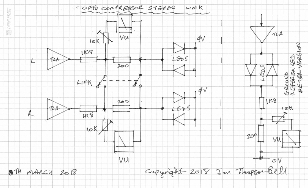
I have given stereo linking some thought and I think the best way to do it is to link the control voltages, but this needs to be done in such a way that each TLA sees the same load as when not linked, and also the two GR meters must still indicate sensibly. I think the attached schematic achieves this:

optolink.jpg


First I split the usual 2K series resistor into a 1K8 and 200 ohm parts. This is based on the assumption that the maximum current we want to drive through the LEDS is 10mA in which case each TLA will be providing 20V rms. The VU meter is connected across the 200 ohm resistor which will have a maximum voltage of 2V rms across it. Since the nominal sensitivity of a VU meter for 100% deflection is about 1.75 volts we add a series trim pot of 10K instead of the usual 3.6K resistor so we can set 100% deflection to 20dB gain reduction (say).

To link the two compressors we connect the two 200 ohm resistors together at both ends. As we are now driving two sets of LEDs, the current through the two 200 ohm resistors can now be as much as 20mA but, because they are in parallel and are now therefore only 100 ohms, we still get the same voltage drop to drive the VU meters as we did before they were linked. Each TLA load is still almost the same as it was unlinked except the 200 ohms has become 100 ohms. Each TLA can still provide a maximum of 10mA into the LEDs as before.

Ignore the little extra sketch on the right. This was an attempt to 0V reference the VU meter so it could easily be switched to read the output instead of gain reduction. However, it does not link the two channels properly so it will not work. In any case, you only need a DPDT switch to switch both ends of the VU meter.

Cheers

Ian
 
Thanks, Ian, your explanation really helps clear up a lot of my confusion - I'm learning much from your posts!

I have one last question before I start placing orders for parts: there was a brief discussion early in this thread regarding similarities with the D-OAC compressor. One of the popular mods is the addition of LEDs and/or resistors in parallel to the vactrols in order to provide  options for altering the compressor's slope. It seems like it could be a useful add-on here. Is there any reason not to give it a try?

Ralph
 
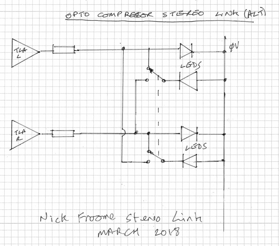
I haven't read all the posts in this thread but had an idea: if you're using two LEDs per channel to drive the Opto, why not stereo link them by swopping sides for two of the LEDs?

So, in mono, the L channel uses LEDs L1 & L2 (and R uses R1 & R2), but, in stereo, L uses L1 & R2 and R uses R1 and L2

That way each opto gets an optical sum of the two sidechains

Nick Froome
 
The D-OAC has a fundamental design flaw. As designed it does not compress because the opto LED and the capacitor driving it form a simple charge pump. All that happens is the cap gets charged up. You need a reverse diode across the Vactrol LED for it to work at all.

It is not clear what, other than the Vactrol characteristics, affect the compressor slope so by all means experiment with additional components to see what effect they have.

Cheers

Ian
 
pvision said:
I haven't read all the posts in this thread but had an idea: if you're using two LEDs per channel to drive the Opto, why not stereo link them by swopping sides for two of the LEDs?

So, in mono, the L channel uses LEDs L1 & L2 (and R uses R1 & R2), but, in stereo, L uses L1 & R2 and R uses R1 and L2

That way each opto gets an optical sum of the two sidechains

Nick Froome

That is a good idea. I think I mentioned it in passing many posts back or in the other thread but it is definitely worth revisiting for its elegant simplicity.
Cheers

Ian
 
ruffrecords said:
... It is not clear what, other than the Vactrol characteristics, affect the compressor slope so by all means experiment with additional components to see what effect they have.

Cheers

Ian

Thanks, Ian. I think I'll focus on getting everything working first and leave further tinkering for later.

Ralph
 
rmaier said:
Thanks, Ian. I think I'll focus on getting everything working first and leave further tinkering for later.

Ralph

Good idea. Build the railroad to the foothills before tackling the mountain.

Cheers

Ian
 
Yes, sage advice.

I've just placed an order for tubes as well as transformers from Edcor (these are built to order and may take up to 8 weeks, so it will be a while before completion). I've also put a Mouser BOM together that I'll double-check (I always manage to forget one or two items and end up placing multiple orders!).

I'm going to power the unit with the external PSU I built for my 4-pack of Classic Preamps. It's pretty robust, so I doubt power will be an issue, even running multiple devices.

Really looking forward to this build! I'll post progress notes and questions as they arise (I'm sure there will be a few...)

Ralph
 
ruffrecords said:
That is a good idea. I think I mentioned it in passing many posts back or in the other thread but it is definitely worth revisiting for its elegant simplicity.

You have to use a DPDT switch to do it. There's a switch which does exactly this job - called an intermediate switch - used for 2-way switching of lights in house wiring. It has two ins and two outs. Don't know if there's an equivalent in electronics

There's another version which is an intermittent, push-to-operate , intermediate switch... for car electric windows

Nick Froome
 
Thanks, Nick. I was just pondering this as you posted, so I sketched it out below. Is this what you mean?

Ralph

Edit: attachment removed. Reason: unclear.
 
Back
Top