- Joined
- Jul 15, 2009
- Messages
- 2,306
Hi GroupdiY,
Lately i was working with Oliver with his consent To make a little PCB kit to Build his version of the U47 with EF800 tube.
As you may already know Oliver passed away but I decided to go ahead and finish it in his memory.
This mic once finished will be called the OA tribute U47.
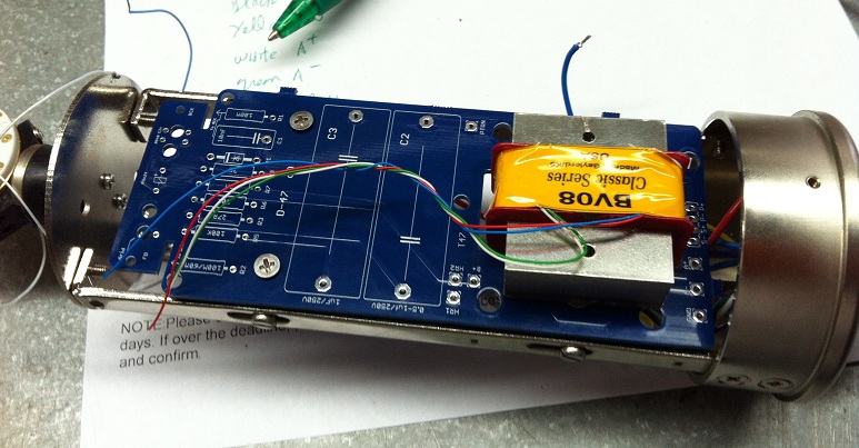
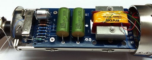
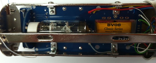
here some partial insight on the construction , the mic will be using Oliver Clasic BV08 series Transformer and Ef800 tube that he personnaly sent to me , I am honnored, I could never thank Oliver enough.
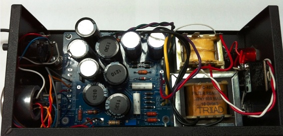
PSU

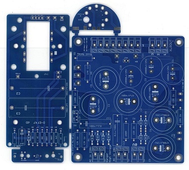
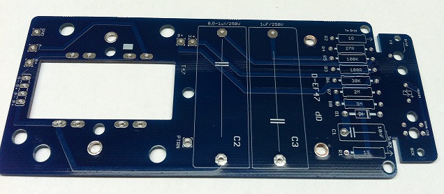
PCBS
Mic
To be continued.............
Best,
Dan,
Hi All, Just finished Final Testing this microphone, Everything Works as expected and I am incredibly happy with the sounds of this microphone


 , Many thanks To Oliver for this Awesome Creation.
and one of the most impressive thing not to say the least this microphone is Incredibly QUIET with this Ef800 Telefunken tube in it ,
This kit will b able to Drive Ef800 , eF802 and Ef80 Telefunken tubes
Absolutely Love it.
I am opening the Kit to the DIY community as we speak, there is some minor Adjustemet I had to do with the PSU resistance Value
there is notes on the Shared mouser BOM about Those changes.
PSU PCB SilK Errata
Needs to be
H+
R2 = 6.8ohm 3W
R6 = 4.7 ohm 3W
R11 = 4.7 ohm 3W
B+
R1 = 20K 2W
R3 = 20K 2W
R8 = 25K pot.
This Project need to be adjusted to B+ 105V and H+ to 5.05V as Per Oliver Schematic
Make sure you Follow the component number on the schematic that is posted here , they are not the same as Oliver schematic
The BOM do not contains the Reed Switch but are available at those location ,
the PCB is designed to support these 2 Reed Relay 24V and 48V, Only one resistor is specifically used on the psu for 24V or 48V relay. Notes are in the BOM as well, Rcoil Relay on the Psu denotes the resistance for either 24V operation or 48V operation.

48V Shielded Reed Relay Available in the Order Page within the D-47 or D-EF47 order Selection box
http://www.vintagemicrophonepcbkit.com/orders.html
Link to alternative 24V Relay
http://www.digikey.ca/product-search/en?vendor=0keywords=7101-24-1010 Relay Coto PN 7101-24-1010
Here is the tubes datasheet for this project,
https://cdn.groupbuilder.com/groupdiy/u/39511/58d1402a070fa.pdf
https://cdn.groupbuilder.com/groupdiy/u/39511/58d1402a0710a.pdf
https://cdn.groupbuilder.com/groupdiy/u/39511/58d1402a0711b.pdf
The Silk Screen will be corrected on the next Batch if Any,
The PCB was specifically design to have package for AMI BV08 Classic Series and AMI T47 Transformer ,
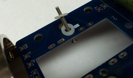
Other transformer can be fitted as well. Here is the 2 Mounting Strategies that will permit the Use of about any transformer.
https://cdn.groupbuilder.com/groupdiy/u/39511/58d1402a0712b.zip
could not be happier with this Toy,
Thanks Oliver.
Hope you will enjoy,
Best,
Dan,
Schemo Mic
https://cdn.groupbuilder.com/groupdiy/u/39511/58d1402a0713c.pdf
Schemo PSU
https://cdn.groupbuilder.com/groupdiy/u/39511/58d1402a0714e.pdf
BOM Psu
https://ca.mouser.com/ProjectManager/ProjectDetail.aspx?AccessID=acb9dba578
BOM Mic
https://ca.mouser.com/ProjectManager/ProjectDetail.aspx?AccessID=f104b8493a
D-EF47 Schematic Thanks toTrans4Funk1
https://cdn.groupbuilder.com/groupdiy/u/39511/58d1402a0715f.pdf
This is Hoe it happened,
Best,
DAn,
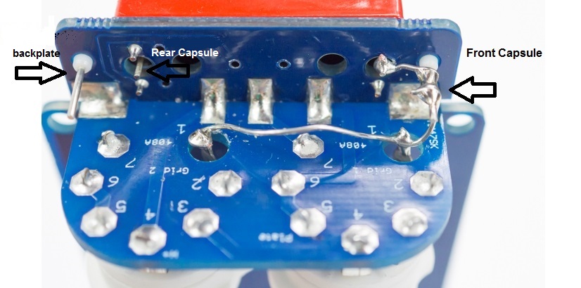
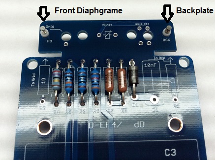
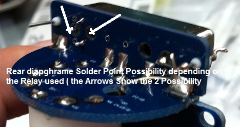
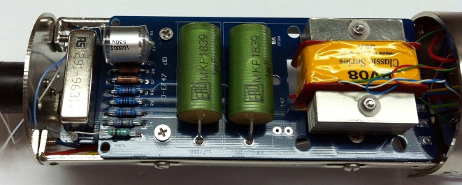
Pictorial.
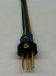
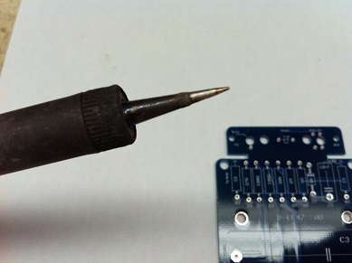
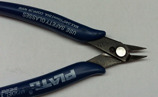
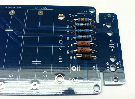
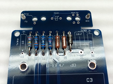
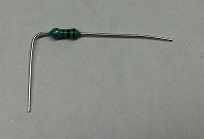
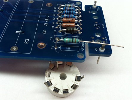
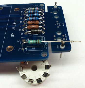
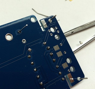
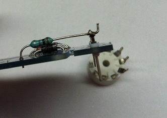
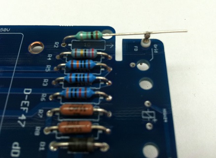
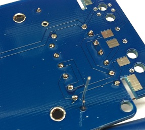
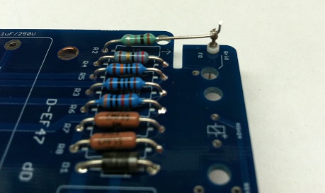
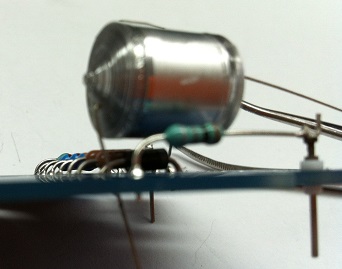
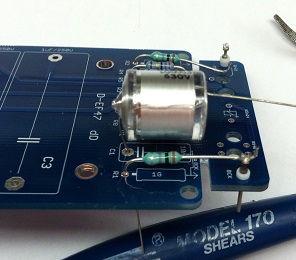
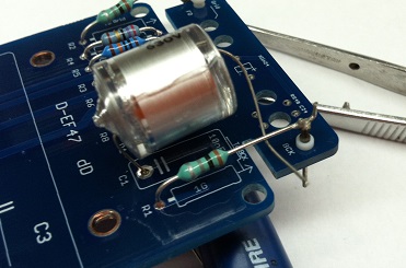
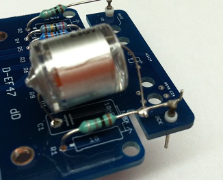
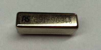
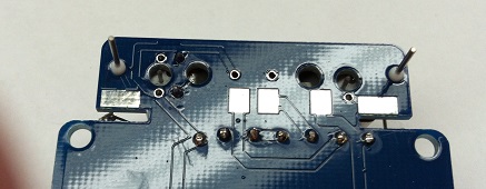
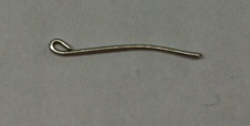
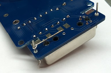
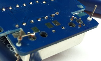
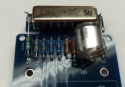
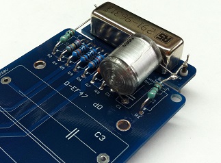
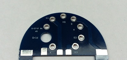
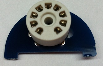
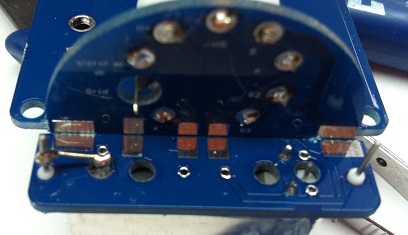
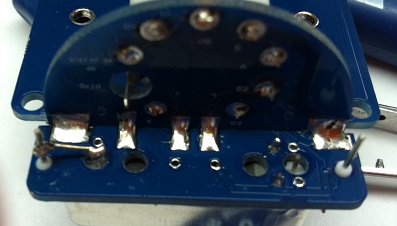
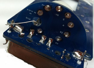
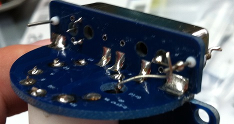
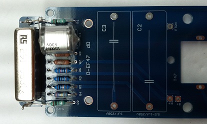
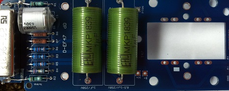
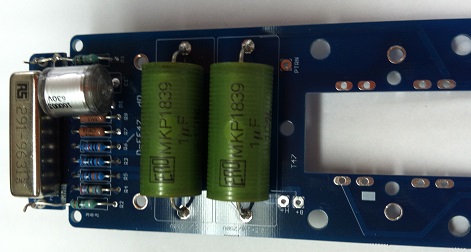
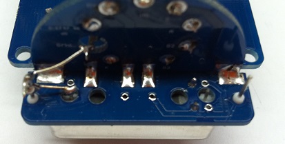
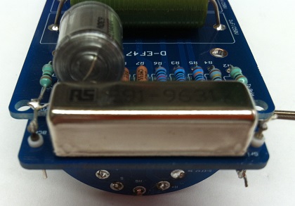
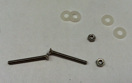
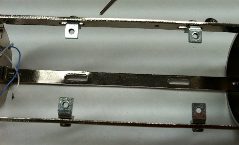

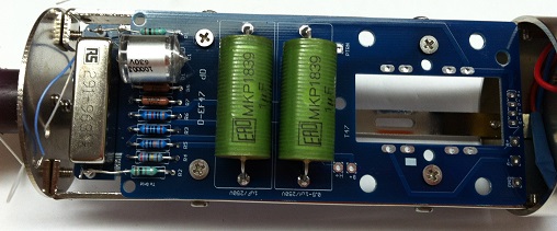

Shown is the D47 dual tube but the principle and connection are the same just forget about the other tube

Best,
DAn,
Lately i was working with Oliver with his consent To make a little PCB kit to Build his version of the U47 with EF800 tube.
As you may already know Oliver passed away but I decided to go ahead and finish it in his memory.
This mic once finished will be called the OA tribute U47.
here some partial insight on the construction , the mic will be using Oliver Clasic BV08 series Transformer and Ef800 tube that he personnaly sent to me , I am honnored, I could never thank Oliver enough.
PSU


PCBS

Mic

To be continued.............
Best,
Dan,
Hi All, Just finished Final Testing this microphone, Everything Works as expected and I am incredibly happy with the sounds of this microphone
and one of the most impressive thing not to say the least this microphone is Incredibly QUIET with this Ef800 Telefunken tube in it ,
This kit will b able to Drive Ef800 , eF802 and Ef80 Telefunken tubes
Absolutely Love it.
I am opening the Kit to the DIY community as we speak, there is some minor Adjustemet I had to do with the PSU resistance Value
there is notes on the Shared mouser BOM about Those changes.
PSU PCB SilK Errata
Needs to be
H+
R2 = 6.8ohm 3W
R6 = 4.7 ohm 3W
R11 = 4.7 ohm 3W
B+
R1 = 20K 2W
R3 = 20K 2W
R8 = 25K pot.
This Project need to be adjusted to B+ 105V and H+ to 5.05V as Per Oliver Schematic
Make sure you Follow the component number on the schematic that is posted here , they are not the same as Oliver schematic
The BOM do not contains the Reed Switch but are available at those location ,
the PCB is designed to support these 2 Reed Relay 24V and 48V, Only one resistor is specifically used on the psu for 24V or 48V relay. Notes are in the BOM as well, Rcoil Relay on the Psu denotes the resistance for either 24V operation or 48V operation.

48V Shielded Reed Relay Available in the Order Page within the D-47 or D-EF47 order Selection box
http://www.vintagemicrophonepcbkit.com/orders.html
Link to alternative 24V Relay
http://www.digikey.ca/product-search/en?vendor=0keywords=7101-24-1010 Relay Coto PN 7101-24-1010
Here is the tubes datasheet for this project,
https://cdn.groupbuilder.com/groupdiy/u/39511/58d1402a070fa.pdf
https://cdn.groupbuilder.com/groupdiy/u/39511/58d1402a0710a.pdf
https://cdn.groupbuilder.com/groupdiy/u/39511/58d1402a0711b.pdf
The Silk Screen will be corrected on the next Batch if Any,
The PCB was specifically design to have package for AMI BV08 Classic Series and AMI T47 Transformer ,
Other transformer can be fitted as well. Here is the 2 Mounting Strategies that will permit the Use of about any transformer.
https://cdn.groupbuilder.com/groupdiy/u/39511/58d1402a0712b.zip
could not be happier with this Toy,
Thanks Oliver.
Hope you will enjoy,
Best,
Dan,
Schemo Mic
https://cdn.groupbuilder.com/groupdiy/u/39511/58d1402a0713c.pdf
Schemo PSU
https://cdn.groupbuilder.com/groupdiy/u/39511/58d1402a0714e.pdf
BOM Psu
https://ca.mouser.com/ProjectManager/ProjectDetail.aspx?AccessID=acb9dba578
BOM Mic
https://ca.mouser.com/ProjectManager/ProjectDetail.aspx?AccessID=f104b8493a
D-EF47 Schematic Thanks toTrans4Funk1
https://cdn.groupbuilder.com/groupdiy/u/39511/58d1402a0715f.pdf
This is Hoe it happened,
Best,
DAn,
Pictorial.


Shown is the D47 dual tube but the principle and connection are the same just forget about the other tube


Best,
DAn,


