Active ribbon-mic

GroupDIY Audio Forum

Help Support GroupDIY Audio Forum:

This site may earn a commission from merchant affiliate links, including eBay, Amazon, and others.
Whoops said:
Please simulate it the other way around also, just in case when tracing I swapped pin1 for pin3 on the transistor.
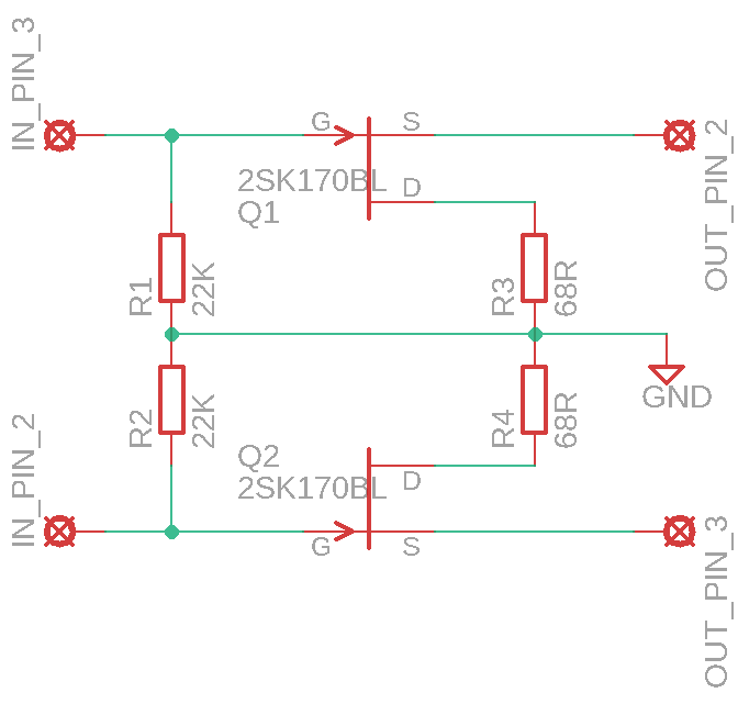
Simulation indicates just a minor gain difference of 0.3dB between the two configurations.
However the model is probably not detailed enough to show the singularities that may happen when swapping pins.
 
Whoops said:
here's the circuit for future reference in case someone needs to repair one:

5iQkKiI.png

Looking at the photos now and re-checking the 2SK170 pinout, I think the D and S are swapped in my schematic,
I think I made a mistake while drawing
 
> For some reason I cannot see the schematic, just some circles?

I can't either. The URL has "google user account", so I tried being logged-in w/Google. Still no see.

"User accounts" on free hosts can be goofy. Another reason to use the Forum image attach system whenever possible.
 
What about drain to gate voltage?
Look at graphs of what happens with drain to gate voltage.

What voltages do the drains measure to ground?

EDIT
this circuit can be improved with about 10 parts depending on what can fit.

CMRR issues
It is about loading impedance not equal signals yes the output going into who knows how well they are matched phantom resistors does not matter as much because the JFET output resistance is set by the drain resistors(the phantom power resistors)
for the 22ks for equal loading of the transformer
JFET for the miller capacitance to the gate
Source resistors for the JFET current
 
PRR said:
> For some reason I cannot see the schematic, just some circles?

I can't either. The URL has "google user account", so I tried being logged-in w/Google. Still no see.

"User accounts" on free hosts can be goofy. Another reason to use the Forum image attach system whenever possible.

I uploaded the photos to imgur, and edited the post with all new photo links.
Please check them now, you will able to see them

The "Forum image attach system" is very limited, I would prefer to use it but you can't insert images between text, you can also only have one image per post, and the way it appears on the screen is very small.
Maybe the way it's implemented can change in the future, that would be great
 
Gus said:
EDIT
this circuit can be improved with about 10 parts depending on what can fit.

It might, but it works nicely the way it is and it's small and simple enough.
For my purposes it sound completely fine, the Timbre was good as was the noise floor, couldn't really listen to any added noise.

The only thing that really bothered me was that for the price (70€) it was really badly made, I couldn't believe how horrible was the soldering when I opened it.
 
Whoops said:
The "Forum image attach system" is very limited, I would prefer to use it but you can't insert images between text, you can also only have one image per post, and the way it appears on the screen is very small.

If you click the thumbnail, it embiggens. (Sometimes way too much!)

I'm not sure how many in-text images are really needed. But when I didn't do my advanced degree ALL images had to go at the end of your theses, no MS Word to stick them between words.

But you can in-text an image attached here:
https://groupdiy.com/index.php?topic=73402.msg929221#msg929221
 
EDIT
this circuit can be improved with about 10 parts depending on what can fit.
Gus, I am interested in what you can up with.
 
Hey everyone, I'm planning on making PMM's schematic on page 5 of this thread with a pair of BD139s as suggested on page 14 (the lowest noise per db of gain in that chart), without the two capacitors.

My only confusion is with the point labeled "Bias" on the schematic. In practice, where is this going to be connected? Pin 1 of the input XLR?

Thanks! I'll post pictures when I do make it.
 
I should mention that the schematic in this thread is misleading,, Drains should be connected to  output Pins 2/3,  and Sources to the 68 ohm resistors.

I've built one, and it works.
If anyone wonders if the FetHead is silent,, it's not,, it adds a few db noise.
I find my Focusrite Saffire 24 quieter at full gain (60db) than using a FetHead to produce the same level from a 1k sinewave played through a monitor.

Watch this:
https://www.youtube.com/watch?v=T8HwNnJAjbQ
 
James-F said:
I should mention that the schematic in this thread is misleading,, Drains should be connected to  output Pins 2/3,  and Sources to the 68 ohm resistors.
(While you could still have a functioning circuit,) for the most recently posted schematic , as here on this page: yes indeed. For previous ones on earlier pages of this thread I don't recall D/S swaps though.

I've built one, and it works.
If anyone wonders if the FetHead is silent,, it's not,, it adds a few db noise.
I find my Focusrite Saffire 24 quieter at full gain (60db) than using a FetHead to produce the same level from a 1k sinewave played through a monitor.

Watch this:
https://www.youtube.com/watch?v=T8HwNnJAjbQ
Thanks for sharing your experiences, and last but not least, welcome here!

Could well understand the statement of the YT-clip you posted.
The trigger for me to start this thread back then was the curiosity of what kind of circuit Royer would be using in their active ribbon mic, so not the add-inbetween gizmo's that have appeared on the market.

I figure it depends on the application; possibly the resulting 'system' with inserted amp-stage does not necessarily improve overal specs (if at all), but might just improve a perceived 'something' (or for instance simply improve the 'system' by eliminating some mic-to-preamp mismatch by inserting such a stage).  As an illustration for this, I recall articles in a German magazine by fellow GDIYer Rossi where he observed benefits by using an 'inbetween' for non-ribbon dynamics like (IIRC) MD421 and/or MD441.
 
clintrubber said:
The trigger for me to start this thread back then was the curiosity of what kind of circuit Royer would be using in their active ribbon mic, so not the add-inbetween gizmo's that have appeared on the market.
GoBo's like Fethead/Cloudlifter have to adapt to a microphone of 150/200 ohms impedance; it is quite difficult because typically the optimal source impedance for the type of circuit they use is around 500-800 ohms. The resulting noise factor is commonly 3-9dB. That's how much the S/N ratio is degraded. Compare to a good mic preamp set at 60dB gain, where the noise factor is about 1-4dB.
That's a strong incentive for not using the same approach for built-in electronics. An excellent noise factor of about 2dB can be achieved by using a different transformer, one that would have a secondary impedance of about 2-5 kohm.
 
Whoops said:
Looking at the photos now and re-checking the 2SK170 pinout, I think the D and S are swapped in my schematic,
I think I made a mistake while drawing

1. Is this drawing okay now? Or do i have to swap D and S?

2. I am a bit irritated because triton audio claims to have 4 matched fets in each fethead.
https://www.tritonaudio.com/fethead.html
 

Latest posts

Back
Top