Transformers for U47/U67/M49/M50 and other Microphones

GroupDIY Audio Forum

Help Support GroupDIY Audio Forum:

This site may earn a commission from merchant affiliate links, including eBay, Amazon, and others.

Marik

Well-known member
Joined
Jun 3, 2004
Messages
1,745
Location
Salt Lake City
Finally we found a good core for transformers, which would work very well in U47/U67/M49/M50 clone microphones and be an excellent replacement for BV8/BV11/BV12 types of the transformers. It has the same side ratio of 1:1.16 of original core, but smaller size helps reducing winding DCR and has greater low level resolution. It also can be used in smaller diameter mics, such as U87, C12, Elam250, etc., without sucrificing specs inherent to small transformers, traditionally used in those microphones.

It is a dual bobbin chambered design with humbucking connection (as original BV8). It has very low DCR, low losses, low phase shift, high overload on low frequencies, and excellent square wave response.

The specs are:

Primary DCR (for 1:8 ratio) 140 Ohm
-0.14dB @ 20Hz
-3dB @ 171KHz
Phase shift -7.5 degree @ 20KHz
Maximum level on primary @ 20Hz =5V RMS

Core size 1”x1.16”, 3/8” stack
Size of the PCB “window” for the bobbins: 0.5”x1.56”

Price: $165 plus shipping.

Best, M
 
Great news Mark,
i beleive this will be a great addition to current microphone projects arround here ,
and what i specially love about this is that it gives even more option for great sounding transformers.
Cant Wait to try those as well.
PMed,

Best,
Dan,


Here is a picture of our take on BV8 with 6.5:1 ratio. Please keep in mind,  if you leave original voltages and tube operating conditions then this ratio is not good for tubes like EF42/95/80/800/802/804/806 and some others often used in U47 projects. Because of impedance mismatch (which often can be quite severe) there are all kinds of sonic anomalies, such as weak bass, weird top, lack of transparency, and so on. For those tubes we are winding custom ratios using the same topology as original BV8 (i.e. chambered, with humbucking connection).

Best, M
 

Attachments

  • BV8.jpg
    BV8.jpg
    25 KB
As with your ribbon mic transformers I'm sure these are nothing short of amazing! 8)
 
Marik said:
Here is a picture of our take on BV8 with 6.5:1 ratio. Please keep in mind,  if you leave original voltages and tube operating conditions then this ratio is not good for tubes like EF42/95/80/800/802/804/806 and some others often used in U47 projects. Because of impedance mismatch (which often can be quite severe) there are all kinds of sonic anomalies, such as weak bass, weird top, lack of transparency, and so on. For those tubes we are winding custom ratios using the same topology as original BV8 (i.e. chambered, with humbucking connection).

Best, M

Can you please explain this Marik? I am using an EF802 in my U47, but the operating point is not the same as the VF14 U47. Plate voltage is about 50V, not 35V, for example. At 35V, it seems the output impedance of the tube would certainly be much higher unless you also increased the grid closer to 0V (or lowered the voltage on the cathode, int he case of the U47).

Also, do you have plans to make a T14/1? We have options for the Hiller T14, but the vintage Haufe T14/1 was different.

With your BV8, does lowering the coupling cap increase the bass response? That is something Oliver said was unique about the BV8, although I am yet to test it with his BV8.
 
Melodeath00 said:
Can you please explain this Marik? I am using an EF802 in my U47, but the operating point is not the same as the VF14 U47. Plate voltage is about 50V, not 35V, for example. At 35V, it seems the output impedance of the tube would certainly be much higher unless you also increased the grid closer to 0V (or lowered the voltage on the cathode, int he case of the U47).

Hello Melodeath,

If you use B+105V, and lock the grid at -1.1V indeed, the EF802 tube does not work the same way as VF14. However, under those conditions the tube would still find the most convenient way of operation. The main problem, its curves are so close to the bending knees of operation that any deviations result in severe changing its characteristics. Since the Rp=∆V/∆I in that region of operation the Rp is very sensitive. The best way to determine the transformer ratio is just to measure the actual circuit output impedance and then calculate the optimum ratio.

Melodeath00 said:
Also, do you have plans to make a T14/1? We have options for the Hiller T14, but the vintage Haufe T14/1 was different.

The short answer is "NO". After all, that was a small, based on DU core, cheap transformer, which somehow found its way to the one of the most sought after microphones (indeed, its HUGE DCR, with monumental phase shift already speaks for itself). Our philosophy is to create the finest transformers with minimum losses and phase shift, to realize the best qualities of the capsule and circuit. Let's put it this way, if you are looking for historical recreation of the Ela  M250/251, then by all means you should use the Haufe (or Hiller, whichever you prefer)! If you are looking for a transformer which would pull out all the best sonic qualities of your brand new Tim Campbell's CK12 recreation in C12, or 251 circuits, we would feel the most comfortable to send you our 12:1 transformer with 15 days return policy, if you are not happy with it.

Melodeath00 said:
With your BV8, does lowering the coupling cap increase the bass response? That is something Oliver said was unique about the BV8, although I am yet to test it with his BV8.

Indeed, the lowish inductance of the BV8 helps to create a resonant bass boost with coupling caps. While I personally do prefer not doing it (after all, any resonant circuits often create more problems than what they solve), we can definitely calculate the transformer to work that way. 

Best, M
 
As is often the case with these matters, there's a certain area of tension between perfection and character.  A big part of  the "charm" of the old mics lies in the arguable imperfections.  Take solving this too far and you'll end up with the modern and sterile sounding  TLM designs.  No chance of that to happen in this case of course, since Marik is transformers.  :p Just stretching the idea to get my point across.

And when you're so good at making trannies, I can imagine it would go against your spirit to build-in deliberate flaws.

BTW, imperfections aside, I personally much prefer a huge BV8 over a tiny Haufe T14/1 (apples and oranges to some extent, I know).
And if it has to be small, yeah, better make it good in all other respects.  ;)
 
Size of the PCB “window” for the bobbins: 0.5”x1.56”

i will be checking if this fits the D-47 and D-EF47 pcbs for sure but IIRC it will ,

Best,
Dan,
 
Marik said:
Hello Melodeath,

If you use B+105V, and lock the grid at -1.1V indeed, the EF802 tube does not work the same way as VF14. However, under those conditions the tube would still find the most convenient way of operation. The main problem, its curves are so close to the bending knees of operation that any deviations result in severe changing its characteristics. Since the Rp=∆V/∆I in that region of operation the Rp is very sensitive. The best way to determine the transformer ratio is just to measure the actual circuit output impedance and then calculate the optimum ratio.

Interesting point. I am using a B+ of 120V rather than 105V, and different plate resistor values. That should bring the operating point "out of the knee" a bit. What do you mean by "the tube will still find the most convenient way of operation?"

Have you measured the actual circuit output impedance of a VF14 U47?

Marik said:
The short answer is "NO". After all, that was a small, based on DU core, cheap transformer, which somehow found its way to the one of the most sought after microphones (indeed, its HUGE DCR, with monumental phase shift already speaks for itself). Our philosophy is to create the finest transformers with minimum losses and phase shift, to realize the best qualities of the capsule and circuit. Let's put it this way, if you are looking for historical recreation of the Ela  M250/251, then by all means you should use the Haufe (or Hiller, whichever you prefer)! If you are looking for a transformer which would pull out all the best sonic qualities of your brand new Tim Campbell's CK12 recreation in C12, or 251 circuits, we would feel the most comfortable to send you our 12:1 transformer with 15 days return policy, if you are not happy with it.

You have a generous return policy. However, as micaddict alluded to, I am aiming at vintage recreations, and I am looking for those transformer imperfections.  I fully understand you not wanting to make a transformer that "isn't very good" on paper, and you may disagree with my "vintage recreation goals." If I wanted to build something new, different, cleaner, etc., I would probably not be building the 251 circuit.

Marik said:
Indeed, the lowish inductance of the BV8 helps to create a resonant bass boost with coupling caps. While I personally do prefer not doing it (after all, any resonant circuits often create more problems than what they solve), we can definitely calculate the transformer to work that way. 

Best, M

So your BV8 DOES work this way, or are you just saying that you could make a custom one that works this way? I am confused.

Thanks!!
 
micaddict said:
As is often the case with these matters, there's a certain area of tension between perfection and character.  A big part of  the "charm" of the old mics lies in the arguable imperfections. 

The interesting thing is that “perfection” and “character” do not contradict each other, but rather go together and feed each other. For example, the same BV8 (unlike T14) is a very refined transformer and it actually has a very strong character. A lot of vintage iconic transformers were very refined and “made right”, still, each of them had a strong character. By “perfection” I mean “made without compromises in implementation” as opposed to “made to somehow work”.

micaddict said:
BTW, imperfections aside, I personally much prefer a huge BV8 over a tiny Haufe T14/1 (apples and oranges to some extent, I know).

Absolutely! Many engineers feel the T14 is a lesser transformer for that microphone.  Precisely the reason we came up with this solution.

Melodeath00 said:
Interesting point. I am using a B+ of 120V rather than 105V, and different plate resistor values. That should bring the operating point "out of the knee" a bit. What do you mean by "the tube will still find the most convenient way of operation?"

Have you measured the actual circuit output impedance of a VF14 U47?

It is hard to say if that brings the operating point out of the knee. There is very little published data for triode connected operation for tubes in that family. The situation is even more complicated because data from different manufacturers can be quite different from each other. On the other hand, the VF14 data in triode connection is widely available and since the tube was coming from the same factory it is very easy to predict its plate resistance from the curves. What I meant by "convenient way of operation" is even if the tube has different characteristics and you put it instead of VF14 in that circuit and adjust 1.1V on cathode it still will find a comfortable way to operate. In this situation it is much easier just measure the output impedance to find correct transformer ratio.

Melodeath00 said:
.

However, as micaddict alluded to, I am aiming at vintage recreations, and I am looking for those transformer imperfections. 

I totally understand your point. That's why I mentioned if you are looking for the vintage recreation then you need to use original transformer.

So your BV8 DOES work this way, or are you just saying that you could make a custom one that works this way? I am confused.

Sorry, I was writing late at night, so wasn't very clear. Our BV8 impedance is the same as original and we scale it for different ratios accordingly. To have a low freq. resonance you should chose the blocking capacitor value around 0.5µF. For our own microphones I prefer not to do this. Since we concentrate more on custom work we can make any transformer specs you wish.

Best, M
 
Marik said:
It is hard to say if that brings the operating point out of the knee. There is very little published data for triode connected operation for tubes in that family. The situation is even more complicated because data from different manufacturers can be quite different from each other. On the other hand, the VF14 data in triode connection is widely available and since the tube was coming from the same factory it is very easy to predict its plate resistance from the curves. What I meant by "convenient way of operation" is even if the tube has different characteristics and you put it instead of VF14 in that circuit and adjust 1.1V on cathode it still will find a comfortable way to operate. In this situation it is much easier just measure the output impedance to find correct transformer ratio.

I totally understand your point. That's why I mentioned if you are looking for the vintage recreation then you need to use original transformer.

Sorry, I was writing late at night, so wasn't very clear. Our BV8 impedance is the same as original and we scale it for different ratios accordingly. To have a low freq. resonance you should chose the blocking capacitor value around 0.5µF. For our own microphones I prefer not to do this. Since we concentrate more on custom work we can make any transformer specs you wish.

Best, M
Wouldn't my mic sound pretty bandwidth limited if it was operating in a very high impedance area of the knee? A triode strapped version of the EF80 has been posted on this forum. If you just put the cathode at about 0.9V instead of 1.1, it would have about the same output impedance as the VF14. If I knew how to make one of those tube charts, I'd do it for the EF800 and EF802.

I would love to use a real vintage Haufe T14/1 in a 251 build, as you say, but they aren't available. This is why I've been seeking out a modern transformer manufacturer for a custom job. I'll probably have the settle for the AMI T14, even though that is based on the Hiller, not the Haufe (Hiller was never used in the ELAM mics).

If you change the ratio of the BV8, does it still have the "BV8 character"?

I am indeed planning to replace the 1uF cap in my U47 with .5uF. I believe it to be more "historically accurate" given the rest of my circuit.
 
Melodeath00 said:
If you change the ratio of the BV8, does it still have the "BV8 character"?

Yes, it does. Even more importantly, BV8 was made to marry VF14. Since we do not use VF14 anymore I'd think that would make a perfect sense to rather optimize the transformer for using with a different tube, rather than take inevitable compromises of mismatching.

Best, M
 
...if Mark's tube-mic trannies prove to be in the same class as his toroidal ribbon-mic trannies, the x-former landscape changes!...
 
Marik said:
The specs are:

Primary DCR (for 1:8 ratio) 140 Ohm
-0.14dB @ 20Hz
-3dB @ 171KHz
Phase shift -7.5 degree @ 20KHz
Maximum level on primary @ 20Hz =5V RMS
Marik, how do you measure your Maximum level on primary @ 20Hz?

Is this 3% THD with the specified source & load resistance?
 
ricardo said:
Marik said:
The specs are:

Primary DCR (for 1:8 ratio) 140 Ohm
-0.14dB @ 20Hz
-3dB @ 171KHz
Phase shift -7.5 degree @ 20KHz
Maximum level on primary @ 20Hz =5V RMS
Marik, how do you measure your Maximum level on primary @ 20Hz?

Is this 3% THD with the specified source & load resistance?

Hi Ricardo,

That number came from an independent evaluation. The load was specified as 1.6kΩ. I assume it was for 3% THD--I will ask under which conditions it was measured.

Best, M
 
Marik said:
That number came from an independent evaluation. The load was specified as 1.6kΩ. I assume it was for 3% THD--I will ask under which conditions it was measured
Ask him what his source resistance is too.

The usual 50R source resistance of a good signal generator will make a difference for this.
 
ricardo said:
Marik said:
That number came from an independent evaluation. The load was specified as 1.6kΩ. I assume it was for 3% THD--I will ask under which conditions it was measured
Ask him what his source resistance is too.

The usual 50R source resistance of a good signal generator will make a difference for this.

Measured in circuit for 3%THD.

Best, M
 
Hey  Marik Just to let you know I have been measuring up the cut out of the pcb in these 2 designs,
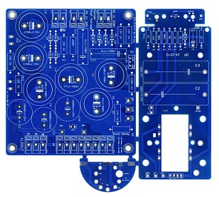
they are (1.57" * 0.74" )  8)  so they could nicely fit those 2 design D-47 dual tube and the D-EF47 as well,

D-47 Dual tube
D47DT%20PCB%20Light.jpg


D-EF47 (EF800-802 tube)
58d0281994413.jpg


as far as the other designs D-47 FET , D-67 , D-269c and D-49b and 49c it wil be possible to have them on board as well,
if you ever make the smaller core BV13 and T14 style for D-12 and D-251 I will be happy to propose them as well.

Best Regards,
Dany,
http://www.vintagemicrophonepcbkit.com
 
Back
Top