culteousness1
Well-known member
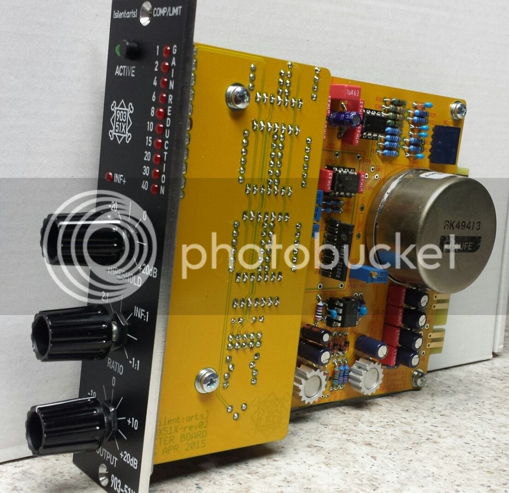
Upacesky said:So the unit is finished, passes audio, sounds clean, the meter is metering, everything's fine!
I just need to calibrate the thing now.
Thanks a lot, the kit was easy to build.
Pictures or it never happened ;D

")