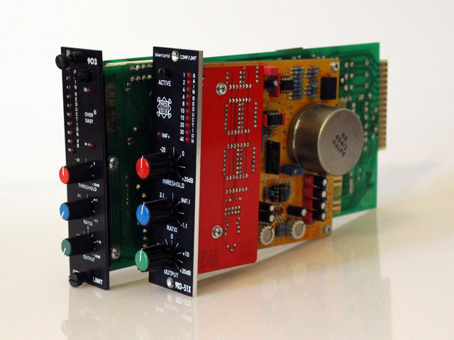
903-51X Comp / Limit

GroupDIY Audio Forum

Help Support GroupDIY Audio Forum:

This site may earn a commission from merchant affiliate links, including eBay, Amazon, and others.
I looked at the 160X schematic and I still think the lower RMS is only going to the meter, but I can't see how the signal gets to the upper RMS detector...  ::)  Was this jumpered to the input like the 903? 

Anyway, one pole of the switch seems to switch between the outputs of 105A alone and 105B + 105A through a 1K resistor.  The other pole connects one input of one of the LM339's to the negative rail, I think, turning on the "above, easy, below" LEDs.  But I don't see any change to the GR metering at all.  Someone with a degree please step in!

Hard knee would mean the CV would ramp up to full value quicker and closer to the threshold, whereas the overeasy is supposed to slowly start ramping up before you actually hit the threshold, IIRC. 
 
OK, I took a shot at tracing out the RMS detector to better visualize how the individual diode-connected NPNs were used.  The NPNs are all represented as diodes but marked with a number corresponding to the schematic silent arts posted on the first page:
http://groupdiy.com/index.php?topic=59044.msg750249#msg750249

The circled junctions correspond to the pin numbers of the detector.  Anyway, someone double check this, I had very little sleep last night. 

Thanks for putting up with me, volker!
 

Attachments

  • DBX_903_RMS.jpg
    DBX_903_RMS.jpg
    908.8 KB
BTW,  the 47K above the second opamp, I couldn't tell if it was + or - 15V, but I found a clearer schematic, it should be -15V. 
 
...Tumbleweeds.....

So, I've been looking at THAT app notes and talking to other members, (mainly joaquins), and come to the conclusion that the soft/hard thing is not the RMS but the thresh/rectifier amps afterwards.  If that helps anyone. I'm going to try some changes to my 166, and see if I get anywhere, but it doesn't seem like anyone else is interested in such an obvious improvement to an otherwise great comp..

Other than that, in case you're still working on this, a sidechain HPF would be nice.  Seems DBX had a "contour" switch on some units which seems to be just a passive HPF on the RMS input.
 
I think a reasonable amount of people are interested in the hard knee, however, personally, I don't have anything to say that will help you on this matter.  Looking at Volker's board, there does appear to be some real estate left.  Yes, redesigning things/verifying is a pain, and could be something that Volker isn't interested in. However even if you come up with a mod for your old unit, it seems to be interesting enough to write it down or share.  Anyhow, I'll go back to lurking and learning now...
Patrick

 
I've been busy with other projects, but I do have an interest in this.  I got a little time with some schematics today and have some ideas floating in my head.  Maybe if  I get some time this weekend....

 
Well, I haven't come up with anything yet, just some ideas to try.  For now, it'll have to be with the 166, in a couple of weeks I should have my 903s back.

As for the HPF, a simple 1 pole could be done by placing a cap in series with each leg of the differential input to the RMS.  Or further along, by swapping caps going into the RMS detector.
 
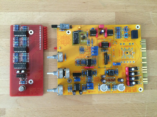
Finally found some time to play with rev02  8)

IMG_1871.JPG


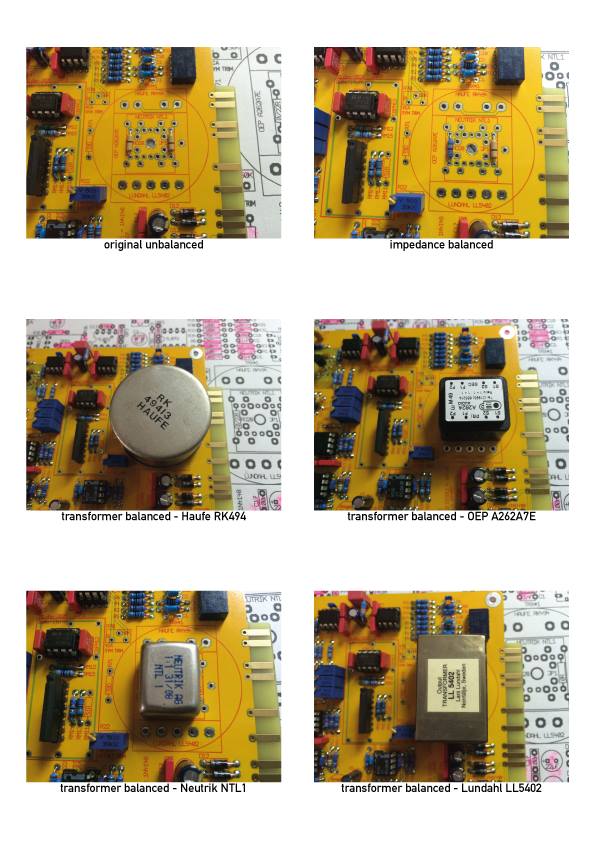
We implemented six different output options:
90X51X-Output-Options.jpg


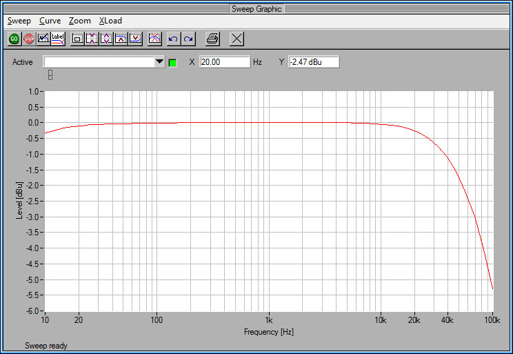
Some measuring (all done with the original unbalanced output version):

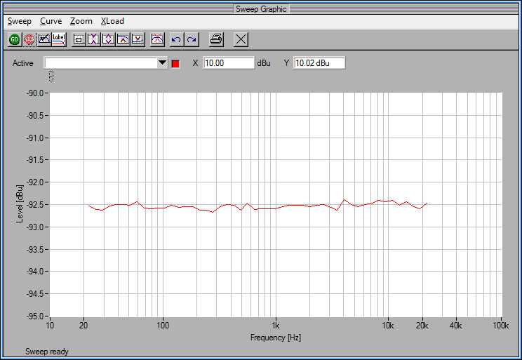
Frequency response:
90351X-Frequency.jpg


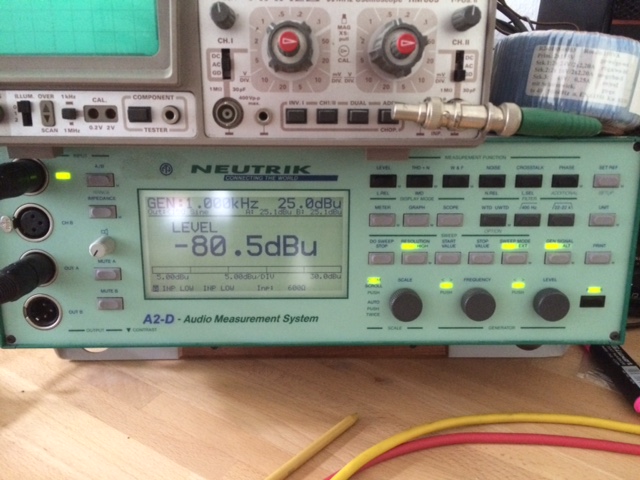
Noise floor:
90351X-Noise.jpg


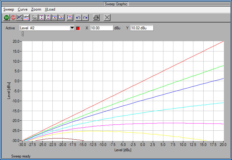
Some gain reduction curves:
90351X-GainReduction.jpg
 
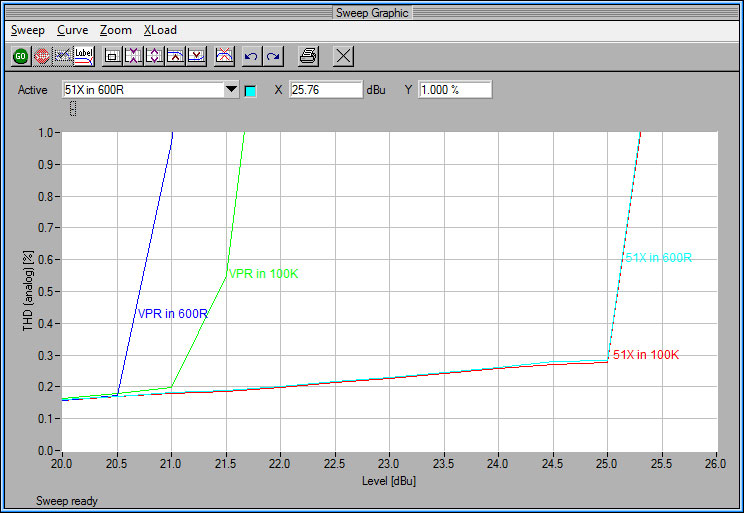
Maximun output level, headroom and dynamic range is different in VPR vs. 51X configuration:
90351X-Output.jpg


but power consumptions is in within specs for both:

VPR, +21dBu into 600R, no gain reduction: +16V = 48mA / -16V = 56mA
VPR, +21dBu into 600R, all LEDs on: +16V = 65mA / -16V = 80mA

51X, +25dBu into 600R, no gain reduction: +16V = 28mA / -16V = 36mA / +24V = 25mA / -24V = 30mA
51X, +25dBu into 600R, all LEDs on: +16V = 50mA / -16V = 36mA / +24V = 30mA / -24V = 35mA
 
Hi Volker,

I'm building the 903-51x and after populating the diodes and resistors, I have some questions:
-R70 is not included, should I worry about it or just leave it open?
-what's the value of R71?
-on the schematic, RM11 and RM14 are 51R, but the bom doesn't say anything about RM11 and I only got one 51R resistor with the kit.  Is RM11 populated?
-What are the little PCB holes inside the footprint of IC2-3 and REL1?
-Why is there an IC footprint over QM22?
- is there something to do for calibrating the unit?

Well, that's a lot of questions, thank you for your answers!
 
- R70 and R71 are not included, and not needed with the provided, pre-trimmed THAT 2180 VCA. Just leave them out.
- RM11 is only for trimm-able VCAs, it is not included and populated for the 2180 VCA
- the little PCB holes inside some footprints are VIAs, just ignore them
- the IC footprint over QM22 is for the original 146221 dbx RMS chip

- calibration: I will adjust the 160XT calibration procedure for the 903-51X today / tomorrow
 
So the unit is finished, passes audio, sounds clean, the meter is metering, everything's fine!

I just need to calibrate the thing now.
Thanks a lot, the kit was easy to build.
 

Latest posts

Back
Top