livingnote
Well-known member
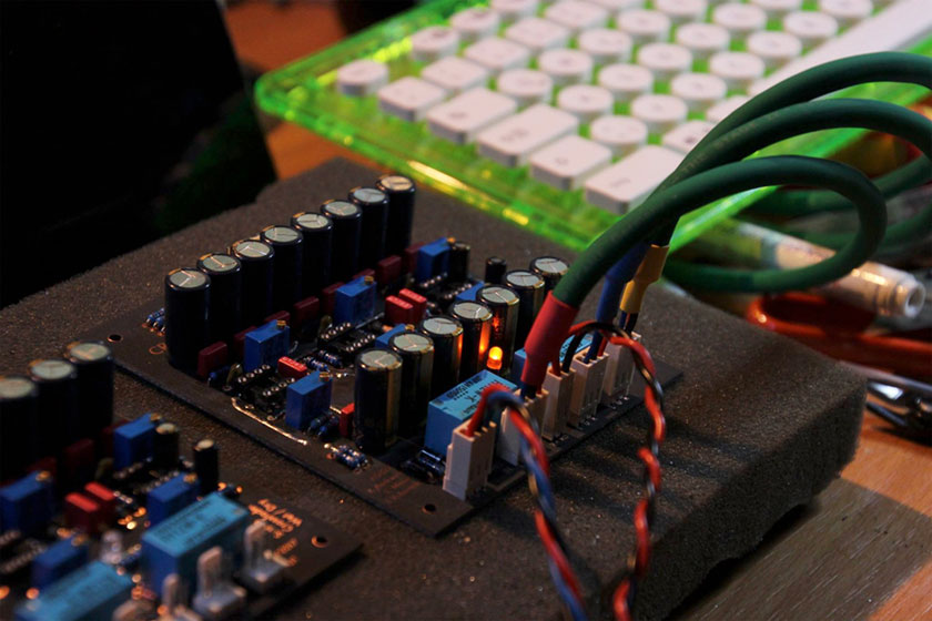
Crush N Blend Rev 6 Crossfader / Wet-Dry Circuit

Measurements (clickable):

Distortion and Noise (A-Weighted):
Level: 12.2 dBu
Freq: 1031.25 Hz
S/(N+D): 0.0038%
THD+N: 0.0023%
Level: 18.2 dBu
Freq: 1031.25 Hz
S/(N+D): 0.0039%
THD+N: 0.0028%
Level: 20dBu
Freq: 1031.25 Hz
S/(N+D): 0.0049%
THD+N: 0.0042%
Distortion takes off around 19.5dBu.
Quiescent current draw ca. 70mA including LED (Class A opamp output operation due to
pull up resistors).
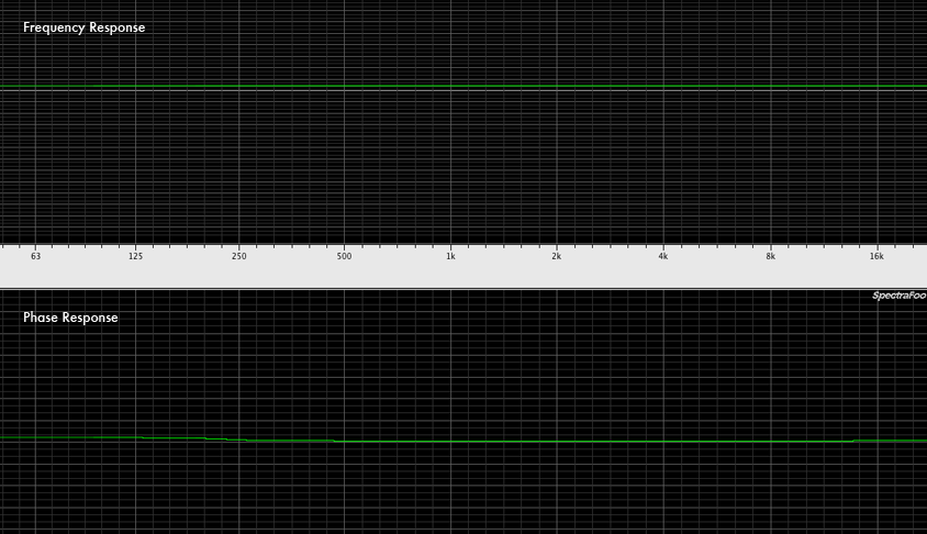
For the graphs above, note there is some fluttering in the meter under about 250-500Hz.
I don't know where that slight phase twist up at 20kHz in bypassed comes from but I surmise
it's a side effect of there being no load on the DAC output going straight back into the input
for measuring. As far as I remember, it did that even when there was no CnB attached at all,
and the input was shorted to the output so...yeah. Looks good.
Changelog:
Power Input protection diodes from last rev now have some added 7.2Ω rail input resistors,
and there's a 10Ω ground plane lifting resistor. There are 100k resistors to ground on all 4 pot
inputs which stabilize the whole construction. Relay Status indicator LED if you want one, and
6 trimmers with a wide enough range to adapt to most "out there" situations.
Also, a push pull dual 10k pot from Alpha has been found - I have them in stock here, along
with small PCBs that output to a standard pin header.
The main mechanical changes were that I got the rivets/vias out from under the component
legs for two reasons:
The "weak" reason for this is because I hate soldering and resoldering stuff that goes through
vias because on industrial boards, you can burn out the barrel and on DIY boards with rivets it's
just a royal p.i.t.a. so I keep them away from component legs.
The "strong" reason is that if you're etching at home and can't lay vias in the form of rivets,
you're screwed, and end up having to rework the board or have ugly caps, relays and trimmers
sticking half out of the PCB. By locating all vias away from the component legs, you can just solder
a wire where the via goes and don't have to worry about components not sitting right.
-> Etch Rats Happy 8)
Construction Documents:
Master File
Etch Separations
Schematic
BOM
Wiring Guide for GSSL
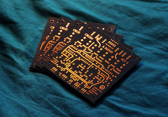
And here is "Das Exquisite Board" from my Etch Lab if you want to order one:

Have Fun!

Measurements (clickable):

Distortion and Noise (A-Weighted):
Level: 12.2 dBu
Freq: 1031.25 Hz
S/(N+D): 0.0038%
THD+N: 0.0023%
Level: 18.2 dBu
Freq: 1031.25 Hz
S/(N+D): 0.0039%
THD+N: 0.0028%
Level: 20dBu
Freq: 1031.25 Hz
S/(N+D): 0.0049%
THD+N: 0.0042%
Distortion takes off around 19.5dBu.
Quiescent current draw ca. 70mA including LED (Class A opamp output operation due to
pull up resistors).
For the graphs above, note there is some fluttering in the meter under about 250-500Hz.
I don't know where that slight phase twist up at 20kHz in bypassed comes from but I surmise
it's a side effect of there being no load on the DAC output going straight back into the input
for measuring. As far as I remember, it did that even when there was no CnB attached at all,
and the input was shorted to the output so...yeah. Looks good.
Changelog:
Power Input protection diodes from last rev now have some added 7.2Ω rail input resistors,
and there's a 10Ω ground plane lifting resistor. There are 100k resistors to ground on all 4 pot
inputs which stabilize the whole construction. Relay Status indicator LED if you want one, and
6 trimmers with a wide enough range to adapt to most "out there" situations.
Also, a push pull dual 10k pot from Alpha has been found - I have them in stock here, along
with small PCBs that output to a standard pin header.
The main mechanical changes were that I got the rivets/vias out from under the component
legs for two reasons:
The "weak" reason for this is because I hate soldering and resoldering stuff that goes through
vias because on industrial boards, you can burn out the barrel and on DIY boards with rivets it's
just a royal p.i.t.a. so I keep them away from component legs.
The "strong" reason is that if you're etching at home and can't lay vias in the form of rivets,
you're screwed, and end up having to rework the board or have ugly caps, relays and trimmers
sticking half out of the PCB. By locating all vias away from the component legs, you can just solder
a wire where the via goes and don't have to worry about components not sitting right.
-> Etch Rats Happy 8)
Construction Documents:
Master File
Etch Separations
Schematic
BOM
Wiring Guide for GSSL
And here is "Das Exquisite Board" from my Etch Lab if you want to order one:

Have Fun!


