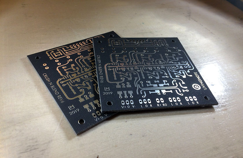
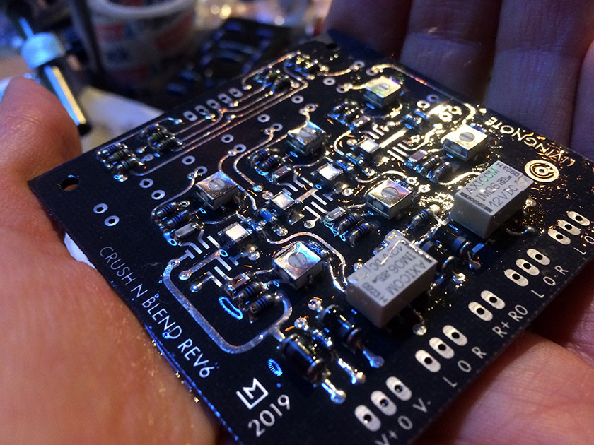
Crush N Blend Rev 6 V3 (CNB / Wet-Dry Circuit) + Support

GroupDIY Audio Forum

Help Support GroupDIY Audio Forum:

This site may earn a commission from merchant affiliate links, including eBay, Amazon, and others.
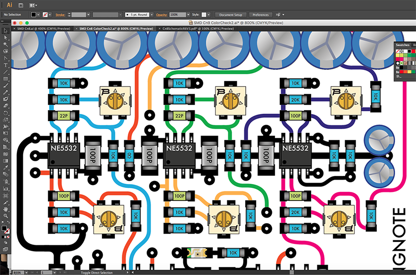
Working on a new SMD version here :)

SMDCNBDesign2.png


In this version, I opted to go with these more simple Bourns Trimmers with J-Hooks:
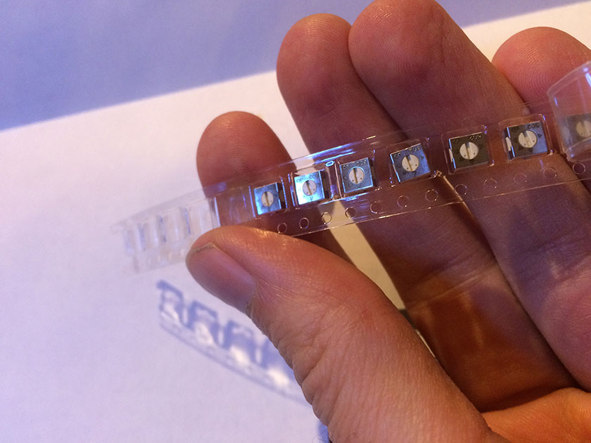
BournsTrimmers.jpg


But what's handy is that there is exactly enough space there to also go with some multi-turn
trimmers like the Vishay T63-YA in case you want more precision and less drift over time.
 
It's been more than 120 days, is this board still available?
Livingnote pm box is full.

If anyone is still visiting, does anyone know of a wet dry solution for thee gssl?

Thanks!
 
Hi livingnote,


Thank you very much for this mod !

I'm making one and have some troubles.

Nothing goes out when switched on.

I'm not sure about the resistors "FBR", what this means ?
I'm not sure about the polarity of the two 1u cap, not clear on the schematic.
I have been able to track the signal until the 22u cap before the NE5532 OUTPUT.
After that the signal is very very low.

And just to be clear, the trimmers are to balance the signal gain between dry and wet isn't it ?

Thank's for any clue !
Cheers

Lars

 
FOUND !!! ;D

The output NE5532 was not feed with +15V.
There was a missing track.
Don't konw why...
See the pic.

Now I heard a problem with the stereo.
I mean when the wet/dry pot is at center position, mix 50/50,
the signal become mono and +6db.
Dry position stereo is good but -6db.
Wet stereo is goos but -6db.

Maybe left right are swapped somewhere... ?
 
I confirm that the Dry Left and Right are swapped from the wiring guide.

Now the board works well.
 

Attachments

  • Capture d’écran 2020-09-06 à 16.16.01.png
    Capture d’écran 2020-09-06 à 16.16.01.png
    109.5 KB
Hey Lars thanks for reiterating the issues - looks like we got them all squashed now.

Patrik had the same problem and we traced them to the same issues you found - wiring
guide and etch documents have been updated and hopefully everything should be working
now, but thanks a ton for being part of the general trying-out of V6.

I'll gladly give you a proto etching session for your work. Just let me know what you
need and you can have 3 medium size boards of the same type free.

Update for everyone with the trimmers:

I have standard here 5K FBRs (Feedback Resistors) with 10K Trimmers on the input
and 10K FBRs with 20 or 22K Trimmers on the outputs, generally (when you want to
be able to trim neg and pos) and you can also just put in a wire link where the FBRs go
and use 20K trimmers on the input and 40-50K trimmers on the output if you need
to have the full range.
 
Hi Lukas,

long time I left this project without solving my issue about +6db on right side when C N B engaged, but with the actual world pandemic, I have time to work on it again...

So I have a simple question... Does your wiring guide applies to GSSL with turbo board ? Mine has TB permanently installed (no on/off switch). I had issue with the TB when installing it and I had to change resistors values that didn't mach between GSSL board and TB board to get L and R side balanced. So, as I have left side -6db when C N B engaged, does that means that I should have taken my left side connexions to C N B from turbo board instead of GSSL board ? At least wet connexion ? Just know that whatever dry or wet knob position it is the same... As soon as C N B engaged, +6db on right side. Maybe dumb question but I've been using my unit without the benefit of the C N B since I installed it because of this unusable 6 db difference from one side to the other.

Did someone ever experience the same problem ?
 
Not sure - and sorry everybody for not being on it more than I was of late
but been rooting around here just getting things working so that the studio
crazies are happy and I can get on with my newly limited job of focusing on
this exact DIY stuff and making PCBs for you guys.
 
I built this project for my GSSL with Turbo and Thrust however the unit doesn't produce unity gain. Even with the 10k resistor at the output section shorted the signal is down 1dB. With the values from the schematic it's maybe -10dB down (770mV in, 240mV out, DRY at max). At mid position there's 3dB gain but I guess that's normal.
So what changes in resistors' values are necessary (if at all) in order to achieve unity gain with DRY at max (effectively in bypass mode)?
 
Hi all ,
On shematic it's 2 film capacitor 1uf no polarised
but on BOM it's 1uF electrolytic capacitors.... what is good ?

What is the meaning of the 2x1uF electrolytic capacitors ?
+ or - Pin to GND ?

regards
 
Hi all ,
On shematic it's 2 film capacitor 1uf no polarised
but on BOM it's 1uF electrolytic capacitors.... what is good ?

What is the meaning of the 2x1uF electrolytic capacitors ?
+ or - Pin to GND ?

regards
Look at picture for orientation of the small 2x1uF electrolytic capacitors middle left.
 

Attachments

  • Screenshot 2021-11-17 0600141.png
    Screenshot 2021-11-17 0600141.png
    1 MB
Back
Top