Gyraf Pultec low end loss

GroupDIY Audio Forum

Help Support GroupDIY Audio Forum:

This site may earn a commission from merchant affiliate links, including eBay, Amazon, and others.

medway

Member
Joined
Jan 23, 2015
Messages
11
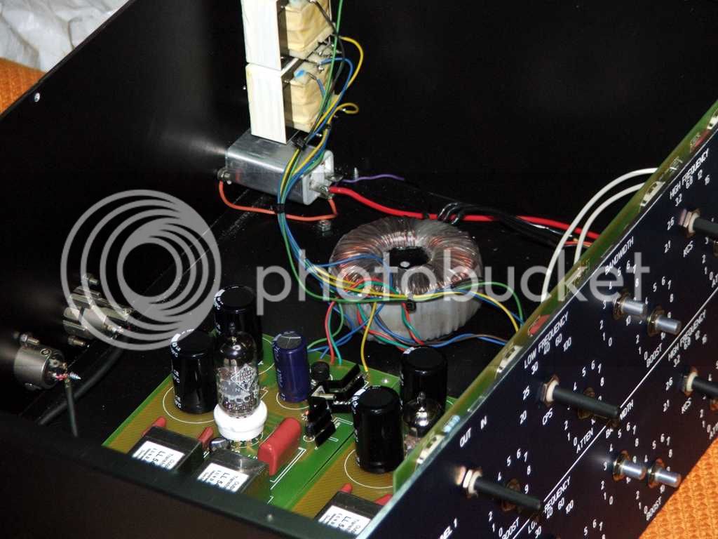
Hi my Pultec has had a slight low end loss ever since I got it about 6 years ago. 

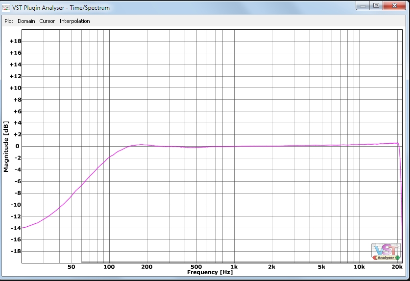
About a year ago I took this freq plot:

ahy9KK1.png


(ignore the top end boost, there is actually a small amount of low end boost too help counter act it as well)

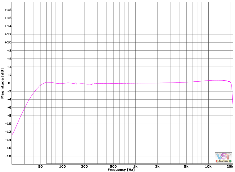
Today I tested it and it's worse, about 2db down at 50hz and 4db at 40hz, almost looks like a butterworth cut filter is across it.

Any idea what this could be? The person who sold it said it was like this from the day he built it so I assumed it was just part of the design but now I'm thinking there's got to be something else that's the cause.

Maybe impedance mismatch? This screenshot was taken with a Creamware Pulsar2 soundcard.
 
medway said:
Any idea what this could be? The person who sold it said it was like this from the day he built it so I assumed it was just part of the design but now I'm thinking there's got to be something else that's the cause.

Maybe impedance mismatch? This screenshot was taken with a Creamware Pulsar2 soundcard.

What gain amp is it using? schematic?
 
ruffrecords said:
Which input transformer does it have?

Cheers

ian

Hi it's 5402's on both the input and outputs as per this schematic:

http://gyraf.dk/gy_pd/pultec/gy_pd_sch.gif
 
MatthisD said:
medway said:
Any idea what this could be? The person who sold it said it was like this from the day he built it so I assumed it was just part of the design but now I'm thinking there's got to be something else that's the cause.

Maybe impedance mismatch? This screenshot was taken with a Creamware Pulsar2 soundcard.

What gain amp is it using? schematic?

Hi excuse my ignorance but would that be the value used?

All I can make out is from the markings is it's a Watson Cryo 6922.

The boards look just like the ones in this pic:

Pultec_inside.jpg


Only difference is the solo blue cap is much larger on mine, 6.3/4700.
 
Just a remark: I think the two output transformers are so close together, that they will interact. (Crosstalk)

(I suppose the two transformers above the mains filter are the output transformers.)
 
medway said:
ruffrecords said:
Which input transformer does it have?

Cheers

ian

Hi it's 5402's on both the input and outputs as per this schematic:

http://gyraf.dk/gy_pd/pultec/gy_pd_sch.gif

OK. The input transformer needs to be driven by a device capable of driving a 600 ohm load. When you tested it, what was driving it?

Cheers

Ian
 
If you want the frequency response to  compare closely to a Pultec you will need to change the input and output transformers. A 1:1 input transformer is probably more practical and an output transformer with higher primary inductance should be used to recover some of the low frequency loss.

There are previous threads with the same complaint which  you should find by searching for ll5402 or G-Pultec.
 
Hi been a few years now and the loss is more, is there some failing component?

PprxqeO.png


This is with the EQ bypassed. Both channels are the same.

Cheers

 
medway said:
Hi been a few years now and the loss is more, is there some failing component?

This is with the EQ bypassed. Both channels are the same.

Cheers

If there are any electrolytic caps in the signal path, they could be failing and cause a loss of low end.
 
medway said:
Hi it's 5402's on both the input and outputs
Have you noticed this transformer has a recommended drive impedance of 15 ohms?
Your soundcard may not be very capable of that.
At the output, even with the two primaries in series, that would be 60 ohms. The SRPP stage that drives it is probably about 10 times this.
It dpoes not mean it can't work, but definitely the LF response is somewhat sacrificed.
 
If your tube looses emission over time, low end can get weak.

I am aware of the design specs for the LL5402 (and have discussed this application with Per Lundall at several occasions) - but the way it behaves in this circuit is really nice. With jan6922's I usually get a -3dB point  between 22 and 28 Hz, which is good enough for most purposes...

Jakob E.
 
gyraf said:
have discussed this application with Per Lundall at several occasions
This is not the first time that a discussion with Per Lundahl has been brought to my attention, and I note that each time the answer is always like "I know it does not appear well adapted, but in the end the result is pleasant".
This is not satisfying to me, it looks like eluding, when I believe there is better explanation.
Now cutting LF at 35-40Hz is actually a good receipe for clean sound, since most of the content below that is garbage.
 
saint gillis said:
Excuse my ignorance, but what would be the effect of some DC voltage flowing through the input transformer's primary? or output transformer's secondary?

Depending upon the magnitude, DC on the primary could bias the core away from its linear region, reduce the incremental inductance, and increase even order distortion.
 
abbey road d enfer said:
This is not satisfying to me, it looks like eluding, when I believe there is better explanation.

Yes, I know exactly what you mean.  Annoys me too.

The conclusion from the discussion(s) was that the data-sheet-recommended drive impedances for the 5402 is about minimizing system distortion, not about lower corner frequency like you traditionally see. And it turns out that there are some (rather big) subjective sonic benefits from running this one sub-optimized - probably has to do with coherence or continuity in distortion signature across low-to-lowmid frequencies..

Jakob E.
 

Latest posts

Back
Top