LED Array constant current array

GroupDIY Audio Forum

Help Support GroupDIY Audio Forum:

This site may earn a commission from merchant affiliate links, including eBay, Amazon, and others.

Rochey

Well-known member
White Market Member
Joined
Jul 2, 2004
Messages
2,697
Location
Dallas, TX - Formerly UK
Jetlagged, in a hotel room, I started thinking about the pain and strife of LED VU Meters, and how they tend to modulate noise on to power and ground lines, due to 10's of mA's being switched on and off rapidly.

I pondered what if we could keep the current constant, so that the system power and ground lines saw the same current being drawn, regardless of LED status.

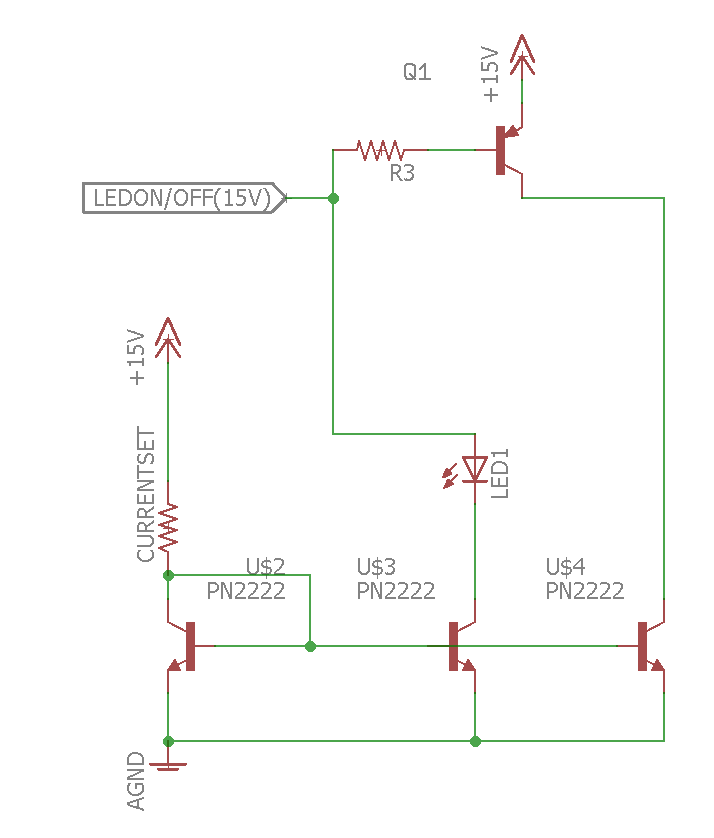
I give you, dun dun duuuuh, the Rochey Constant Current LED Circuit.
A few notes:
  • It's probably been done before.
  • 15V is extreme, you could probably run the ON/OFF from a 5V supply and an inverter/not gate.
  • The current set resistor sets the constant current through the LED array
  • When the LED is off, the same current is driven driven through U$4
  • It's massively power inefficient, but most Pro Audio gear is more concerned with low noise than power consumption
  • Current Set resistor can be used once for your entire LED array, giving consistent LED brightness.

8ePtPCC.png

 
This is also interesting.

Taken from my favorite Mr. Self's Small Signal Audio Design book :)
 

Attachments

  • constant_current_source_led_bargraph.jpg
    constant_current_source_led_bargraph.jpg
    132.2 KB · Views: 55
MBB<

I've seen that schem before. It's excellent, but it relies on the LED's only being serially driven.
You can't switch on a single LED in the middle of the array.

Other than that, it's a very elegant solution. Only needing a single current source is nice.
 
There are two path for the nominal current, so the switching noise will happen in some level, IMO. 

Rochey said:
...It's probably been done before...

Yes. Please look into any Soundcraft analog console schematic. For example:


Attachments

  • led array switch.png
    led array switch.png
    162.1 KB · Views: 37
moamps said:
There are two path for the nominal current, so the switching noise will happen in some level, IMO. 
Yes. Please look into any Soundcraft analog console schematic. For example:

the switching noise is going to be less than 10mA per LED? A smoothing cap would likely cover you for the small change in current.
Also, the soundcraft schem was likely done by Doug Self too. High voltage, single constant current source into the LED string. It doesn't help with parallel LED that can be lit randomly.

or did I miss something?

(By the way, I'm not trying to say this is original in any way... just trying to show that even with CC sources, with LED's, you have to try and shunt the current elsewhere if you want to keep current transitions down).

/R
 
Rochey said:
... It doesn't help with parallel LED that can be lit randomly...
or did I miss something?

Any LED can be controlled independently, with a switch or logic in this case.
 
moamps said:
Any LED can be controlled independently, with a switch or logic in this case.

I see it! :)

The transistors bypass the LED.
I tried designing a similar circuit a few years ago in a simulator and I had the most difficult of times. Main issue what that you end up injecting base current into the emitter. Looking back, I wonder if that was really an issue.

/R
 
Since I got my first patent for a peak/ave LED meter in 1979  (US04166245  Roberts) you can be assured I have explored all the different variants for making LED meters, further in console design current consumption matters when each channel get repeated 36 times, so the current source driving LEDs with shunts across them makes sense...  :eek: 

The last BIG console I did used a dedicated LED meter IC that was already in the system so not that clever, but the meter bridge was it's own self contained metal box so noise was not an issue. That said a typical console channel will have a handful of indicator LED, so they will typically be driven from a current source in series between the rails with shunts across them to turn on/off. That way any commutation current is fully in the rails and never touches ground.

My later effort with microprocessor based LED meters could have been cheaper multiplexing the LEDs (like I did for my drum tuners where noise was not a concern), but inside that later console we drove the LEDs in parallel (latched, picture below). That way the LEDs only switched when changing state. Keeping good PCB layout discipline to control the current loops kept the noise manageable , we had more SPI noise in the noise floor than actual LED meter noise, while SPI was controlling the latches so there will be common frequency terms but the noise floor was not modulated by the display content.

These days they make dedicated digital LED latch decoder drivers, that have current sources built in to minimize parts count, and can be controlled by a serial data com (like SPI). In my current drum tuner I use one 16 LED latch decoder driver, then multiplex that as 3 banks of 12 LEDS with MOSFET high side drivers per bank of 12 so one IC and 3 mosfets control 36 LEDs (I had one line free, so could have controlled another 12 LEDs just didn't have a use for them)  8).

Among the stones I didn't leave untouched, I even made a simultaneous Peak/VU LED meter using the ubiquitous LM3915. To display the peak and VU information  separately I multiplexed the input source, and bar/dot mode... I don't recall what multiplex rate I used because I only built one for my bench just to see if it could be done.  I also made one prototype using a 100 segment vacuum fluorescent display.

JR


Attachments

  • meter_pix.jpg
    meter_pix.jpg
    18.8 KB · Views: 9
Rochey said:
I see it! :)

The transistors bypass the LED.
I tried designing a similar circuit a few years ago in a simulator and I had the most difficult of times. Main issue what that you end up injecting base current into the emitter. Looking back, I wonder if that was really an issue.

/R
It is pretty easy to get transistors with beta > 100 so base current is modest.  Using JFET or mosfet shunts eliminates the base injection current issue.

JR
 
Rochey said:
MBB<

I've seen that schem before. It's excellent, but it relies on the LED's only being serially driven.
You can't switch on a single LED in the middle of the array.

Other than that, it's a very elegant solution. Only needing a single current source is nice.
You can switch devices in the middle of a series string if the shunts are across each LED individually and the gate drive has enough compliance to ignore shifting voltages.

When designing simultaneous Peak/VU meters one useful relationship was that short term Peak is always higher amplitude than VU (average), so that conflict never arose. This ASSumes the same release time for Peak and VU displays, while Peak clearly uses a faster attack time.  In my experience using the same release time for both, and constant dB spacing between LEDs provides a visual Crest Factor display (difference between peak and average) that will remain constant and readable as both decay at the same rate. 

JR
 
metalb00b00 said:
This is also interesting.

Taken from my favorite Mr. Self's Small Signal Audio Design book :)

Note that Doug uses the LM2901 here, and not the more ubiquitous LM339.

Why this matters is an exercise left to the reader :)
 
A shunt regulator is a nice addition to a constant-current LED chain: belt and braces.
Whatever the precautions, there are always current spikes, notably from the comparators switching violently.
There is nothing like not letting these currents (particularly the LED return current) crossing the path of the audio "ground".
 

Latest posts

Back
Top