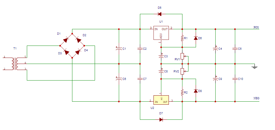
10 amp psu regulator

GroupDIY Audio Forum

Help Support GroupDIY Audio Forum:

This site may earn a commission from merchant affiliate links, including eBay, Amazon, and others.
dogears said:
Hm. So the dirty 0V which is also regulator reference
No. The regulator reference is the clean 0V. 

This also means dirty 0V is floating,
I haven't used the word floating, because that would suggest it's not galvanically connected to 0V. It is actually hanging to 0V by a piece of wire (or PCB track).

but audio and chassis are tied to earth. Is that correct?
Yes.
 
+1 to what Abbey sez....

By definition the regulator ground is the clean 0V node.

It may help you understand the design philosophy if you appreciate that PCB traces have resistance so as predicted by ohms law there will be voltage drops developed across those traces by current flowing in them.

In the case of a typical PS there will be significant current charging the reservoir capacitors. This will cause tiny (ugly) AC voltages across every trace passing that current. The strategy is to just let these tiny voltage drops occur harmlessly in series with paths to and from the power transformer.

The regulator ground reference connects to this common ground node at one point.  Since there is no dirty AC current flowing in this trace it remains a clean 0V reference.

JR
 
Like this, then?

FSipEro.png


C1, C2, C6, C7 tied back to transformer CT. Regulator reference is audio ground, which ties back to chassis and safety ground at one point (not shown).
 
I didn't study every part but it looks like you are missing a ground path between the reservoirs caps/transformer CT to the regulator 0V.

With that path open, any imbalance between +/- supply draw will cause the unregulated to float up/down, no bueno...

JR 
 
abbey road d enfer said:
You need a connection between C2/7 and C3/8

Goodness, now I'm very confused. That's how I have always done it, but I was thinking you were somehow trying to isolate the post-rectifier smoothing caps / transformer center tap node from the regulator reference and audio 0V nodes.
 
I think John gave you the clue:  in your schematic, once you tie those nodes together, then what is the difference?  It looks that way, because, in the schematic, it's one single node that has zero ohms resistance, so, by definition, all points along that node are at the same potential, regardless of the amount of current flowing.

But that isn't really what is happening:  that "ground" line has a (small) resistor in-between each and every connecting node:  thus, it isn't a smooth zero-ohm connection like the schematic depicts.  There is a resistor between the center tap and C1/C8...there's another resistor between C1/C6 and C2/C7, and yet another between C2/C7 and C8/C8.  The magnitude of these resistances are defined by the copper losses in the real wiring, and these resistances mean there are "new nodes" along the ground path.

Go ahead and draw those in, then you'll understand that each of those create new nodes that are all (in reality) at different potentials based on the current flowing through the trace(s) at those points.  It also renders obvious your questioning about where to connect further "grounds" into this matrix of "new nodes".
 
Matador said:
I think John gave you the clue:  in your schematic, once you tie those nodes together, then what is the difference?  It looks that way, because, in the schematic, it's one single node that has zero ohms resistance, so, by definition, all points along that node are at the same potential, regardless of the amount of current flowing.

But that isn't really what is happening:  that "ground" line has a (small) resistor in-between each and every connecting node:  thus, it isn't a smooth zero-ohm connection like the schematic depicts.  There is a resistor between the center tap and C1/C8...there's another resistor between C1/C6 and C2/C7, and yet another between C2/C7 and C8/C8.  The magnitude of these resistances are defined by the copper losses in the real wiring, and these resistances mean there are "new nodes" along the ground path.

Go ahead and draw those in, then you'll understand that each of those create new nodes that are all (in reality) at different potentials based on the current flowing through the trace(s) at those points.  It also renders obvious your questioning about where to connect further "grounds" into this matrix of "new nodes".
Right, re-reading John's last paragraph (connecting to the node at one point) makes it clear.
 
Hi,

More changes!....¿Can anyone point me to a good soft start circuit?. There are many ways to do it... more or less complicated... :p

The trasnformers i will use: 330VA +/-18v  for opamps. 50VA 2X12V for logic circuits.  30VA 2X25V for 48v phantom.
The IEC inlet is rated for 15 amps. A lot of current at startup! :eek:

¡Thanks a lot!

Jay x
 
Hi!,

I think that the current surge is more dangerous for a transformer.  So, a CTN, may be more efective.
¿Would It be good to have both?
Or a CTN is enough?

Jay x
 
I don't think that the soft start is needed for a 300VA transformer at all. Just use slow blow fuse on transformer primary rated for 50% or 100% higher primary current and it should be fine, IMO.  If you really need a soft start, use high power resistor, not NTC, in conjunction with a power relay.

Using NTC here isn't good idea, IMO.
 
The main problem with NTC is that it needs a time after power down for cooling down and for a correct operation after next power up. This time can be several minutes, especially in cases when the power supply is permanently heavily loaded. If, for example, a short main voltage drop occurs, NTC will fail in limiting current, and fuse will blow. This shouldn't happen in a consoles power supply.
In Twin, the most dominant cause of a big inrush current is a very low resistance of cold tube heaters at power up. If a short main voltage drop occurs there after a some time of operation, NTC will fail in limiting current, but this time the inrush current can't be  so high because tubes are still warm. 
 
moamps said:
The main problem with NTC is that it needs a time after power down for cooling down and for a correct operation after next power up. This time can be several minutes, especially in cases when the power supply is permanently heavily loaded. If, for example, a short main voltage drop occurs, NTC will fail in limiting current, and fuse will blow. This shouldn't happen in a consoles power supply.
In Twin, the most dominant cause of a big inrush current is a very low resistance of cold tube heaters at power up. If a short main voltage drop occurs there after a some time of operation, NTC will fail in limiting current, but this time the inrush current can't be  so high because tubes are still warm.
That's why I suggested to have it switched out using a relay. Best of both worlds.
 
> I think that the current surge is more dangerous for a transformer.

Connect your 300VA transformer to your dryer circuit. Short the secondaries. I bet it takes several minutes to start burning.

A part-second "surge" is NOTHING to a transformer. Little trannies have high resistance and not much surge. Big trannies have high mass and take time to heat-up.

The 25,000VA transformer for my house has a rating for much more but at shorter life. If at holiday me and my neighbor both cook wash clean heat to the max and suck 40,000VA for 4 hours, it takes about 12 hours off the nominal life of the transformer. (Since our average load over 20 years is nearer 2,000VA, 8% of rating, that trannie is gonna live a lot more than 20 years no matter how big our turkeys are.)
 
Hi!

Another idea/option for an 8amp PSU is a pass transistor design. I found a schematic  with lm317/337 and bdx53c/54c as pass transistors, with a low value base resistor (10R).

I'm considering different options, before starting melting solder... ;D , and layout seems a bit easier...
 
Back
Top