maxwall
Well-known member
- Joined
- Nov 17, 2004
- Messages
- 1,134
I have always wanted to build a XX73 or XX84 classic but never felt right about the integrity of many boards and schematics circulating across the forums. It does'nt take long to sit down and find that most of them are riddled with error. I could'nt see putting good money and time into a risky layout that may not work as intended. So, here is a place where interested members can share info on DIY board artwork layouts that might be inconsistent with original manufacturers schematic diagrams. In Addition, there are some newer modern components available ( like inductors ) that will require board trace/pad modifications to fit these components on the boards properly. So feel free to post any schematic or board artwork that can eliminate the unintended errors in this project before etching a board for your XX73/84 DIY project.
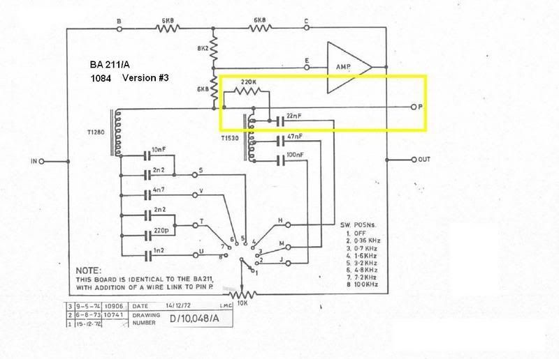
I'll start this thread with some inconsistencies (or board rev changes ) I have found on a DIY BA211 board found on a website we are all familiar with. It was posted by Chris Vallejo who mentioned that there were some issues , but never followed up on what they were. Ever since I stumbled across the artwork, I have yet to see any corrected information surface and have lost my patience waiting for the revised layouts on some of these possibly questionable boards.
So here is what I have found on this first XX73 board. Feel free to contribute to this or add another board and a diagram for debugging.
Corrective PCB artwork is also welcomed.
I have just discovered 3 different versions of the B211 board that need clarification.
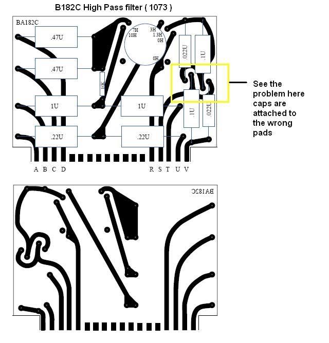
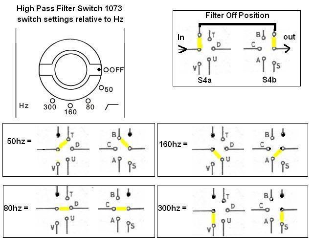
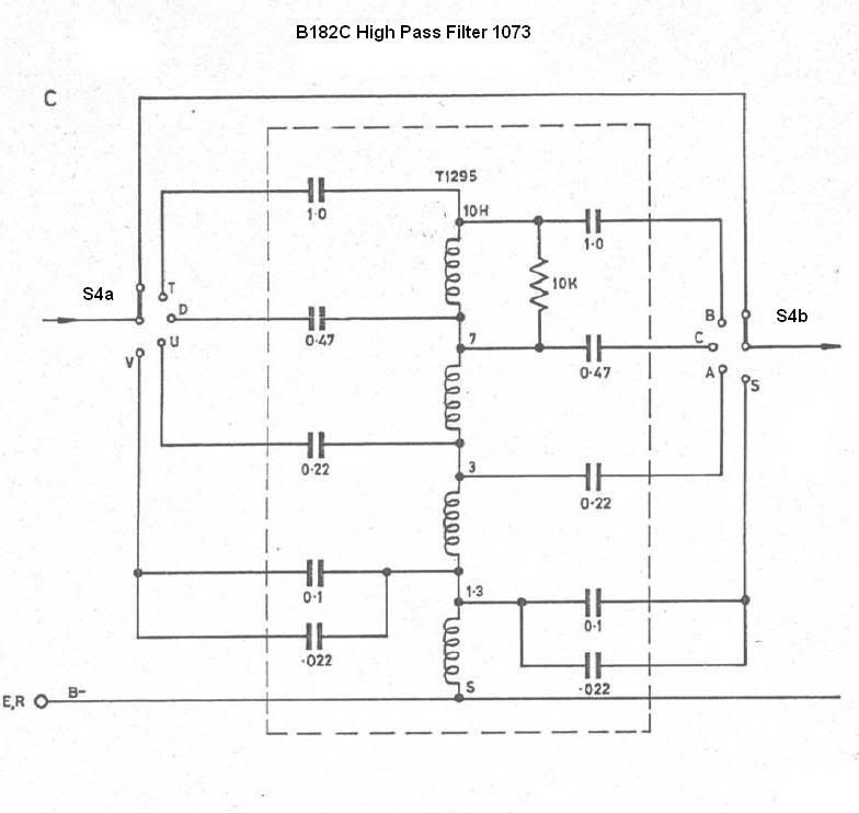
Just added B182C board with inductor T1295/VTB9043 , some minor corrections observed. I've added a switch position diagram that will help
folks understand the filter signal flow. This information can aid in discovering either bad artwork or misplaced component layouts.
Unfortunately, I do not have a 1073 module to compare with.
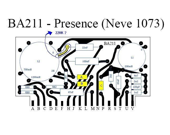
A = not used
B = not used
C = not used
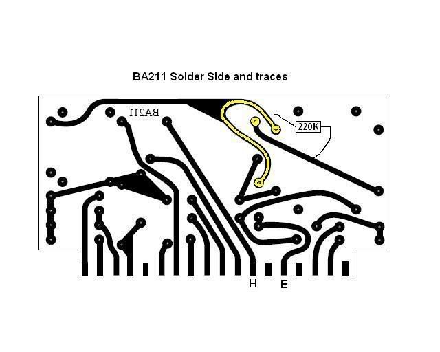
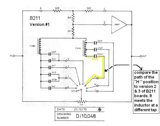
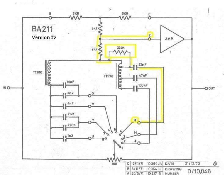
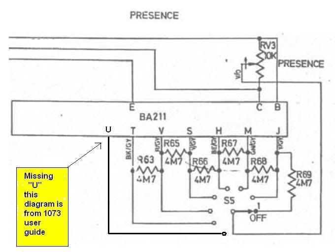
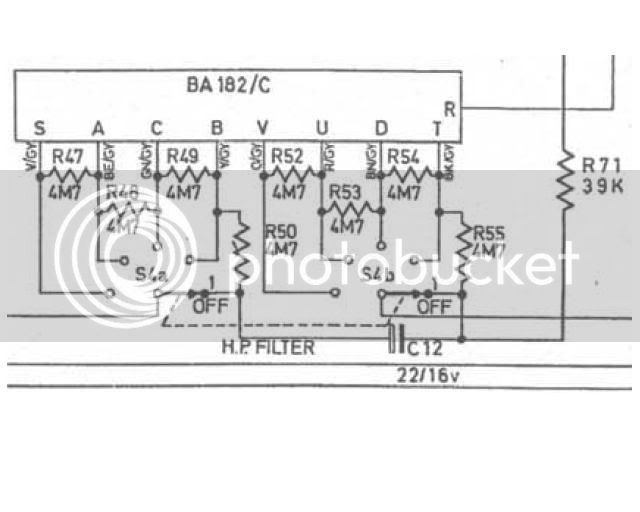
Here is an error I found right out of the Neve 1073/81 user guide published by AMS Neve - can you believe this. see below. If this were
to be installed in a 1084 then "U" is not used.
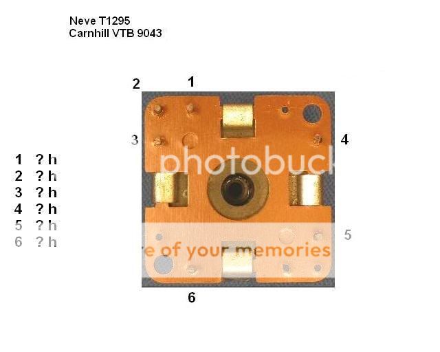
Here is B182C (1073 ) and T1295 inductor for general info and pinouts
I'll start this thread with some inconsistencies (or board rev changes ) I have found on a DIY BA211 board found on a website we are all familiar with. It was posted by Chris Vallejo who mentioned that there were some issues , but never followed up on what they were. Ever since I stumbled across the artwork, I have yet to see any corrected information surface and have lost my patience waiting for the revised layouts on some of these possibly questionable boards.
So here is what I have found on this first XX73 board. Feel free to contribute to this or add another board and a diagram for debugging.
Corrective PCB artwork is also welcomed.
I have just discovered 3 different versions of the B211 board that need clarification.
Just added B182C board with inductor T1295/VTB9043 , some minor corrections observed. I've added a switch position diagram that will help
folks understand the filter signal flow. This information can aid in discovering either bad artwork or misplaced component layouts.
Unfortunately, I do not have a 1073 module to compare with.

A = not used
B = not used
C = not used


Here is an error I found right out of the Neve 1073/81 user guide published by AMS Neve - can you believe this. see below. If this were
to be installed in a 1084 then "U" is not used.

Here is B182C (1073 ) and T1295 inductor for general info and pinouts


![Electronics Soldering Iron Kit, [Upgraded] Soldering Iron 110V 90W LCD Digital Portable Soldering Kit 180-480℃(356-896℉), Welding Tool with ON/OFF Switch, Auto-sleep, Thermostatic Design](https://m.media-amazon.com/images/I/41gRDnlyfJS._SL500_.jpg)
