1073/1084 PCB Debug

GroupDIY Audio Forum

Help Support GroupDIY Audio Forum:

This site may earn a commission from merchant affiliate links, including eBay, Amazon, and others.
1u : dia 17.0 x 31.5
.22u:dia 8.5 x 30.0
22n :dia 6.7 x 18.5
100n :dia 8.7 x 18.0
47n,10n,15n almost same as 22n

b211 :90 x 50 with (9.7 x 7.3) x 2 cutouts for cinch
b283av :90 x 58 with (9.7 x 7.3) x 2 cutouts for cinch
b182c :90 x 70 with (9.7 x 7.3) x 2 cutouts for cinch
b205 :90 x 50 with (9.7 x 7.3) x 2 cutouts for cinch
b284 :90 x 58 with (9.7 x 7.3) x 2 cutouts for cinch

Also if you could please put the component solder pads atleast 3mm inboard after 5mm side trim.This is applicable to only those folks wanting to put .This will ensure that we dont cut through any of the component when trimming the Eurocard.
I think the price is great especially with the gold plating
 
[quote author="maxwall"] which some consider part of the sound would be addressed properly as well. [/quote]

Maxwall I dont believe the profile of the trace routing contributes to the Neeb sound.Audioforge's trace are darn close to the originals and yet not the same.He has made some intelligent design improvements from the original board if you look closely.
 
Audioforge - the mods you added are going to make the build much better without a doubt. And the prices are very reasonable so far :grin:


Codered, Yeah, I agree the trace mods being done are not extreme enough to change the sound much , but I'm only speculating on this and that would open up an entirely exhausting discussion and testing cycle no one really wants to get into on a project like this. So for now it will be fine.

Thanks for posting the board and component dimensions this is great info. I'm assuming those dimensions are off originals.
 
codered
eg b211 :90 x 50 with (9.7 x 7.3) x 2 cutouts for cinch
does this mean 50 mm included the edgeconnectors traces
or it s 50mm + 9.7mm =approx 60mm.

i need to know before redesign all boards to fit in an original case.
that s a lot of work.......
i will try to reduce all boards by 95 mm X 75 to put the 4 mounting holes
but try to keep the trace within the original boards sizes so triming would be possible for thoses wanting put them in an original case.
waiting all others pics critical components sizes and advices you have.
thanks to all of you
audioforge
edit. i redesign b211 and b205. now traces fits in 95mm X 60mm hight. is it enought?(to don t touch your elma 3 decks).i woud have a lot troubles to earn 10 mm less.........
 
http://twin-x.com/groupdiy/displayimage.php?pos=-1830

Hope this helps.
I am sorry you have to modify the boards(more work) but I think we'll have a better end product.
Please let me know what other dimensional information you need.As the modules I have access to are in a production environment (rack or console) , I would like to take measurements all at one when I get a chance.
Also the gold plating is very thin in the original modules and it is not suggested to remove them too many times.I dont know what the optimal thickness is but you might want to specify that to the manufacturer.
 
If you have read the last post i ve done in the groupbuy thread on blackmarket, you allready know i had a hard drives failure at my work :cry: .
i ve lost all my files for my work and the new "reduced sizes" pcbs were in this computer... one of my hd have been sent to a specialized lab for recovery my work files (and the layouts too) but i don t know yet if it could be done.
anyway ,since i had not finished the b284 i ve done it again.
size will be 100mm x 70 mm (due to the b182c size so all the mounting holes are "in line") but the pcb traces size is 95mm x 60mm.
Codered i sent you this file within email. could you check it.
it took me about 6 hours to re do the layout and my eyes cross now.
please post your checking report......
i will work on the others files later this week.
audioforge
 
Audioforge, sorry about those disk files

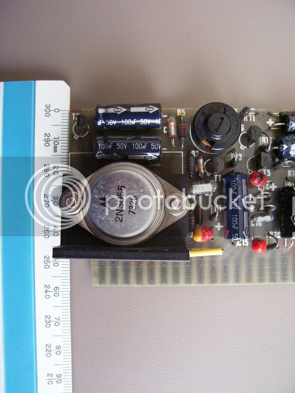
Here is a B283AV original for reference. I can add more shots if needed -just ask.
Original below - I photo'ed this myself.

283AV.jpg
 
maxwal - great thread!

I am also doing some research. I want to start on a pcb for the gain switch.

I have a question maybe someone can clarify for me.

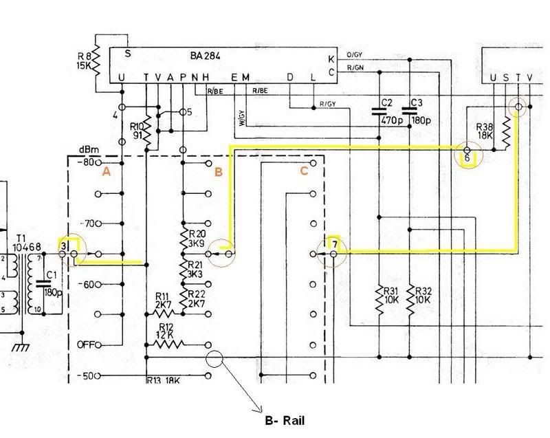
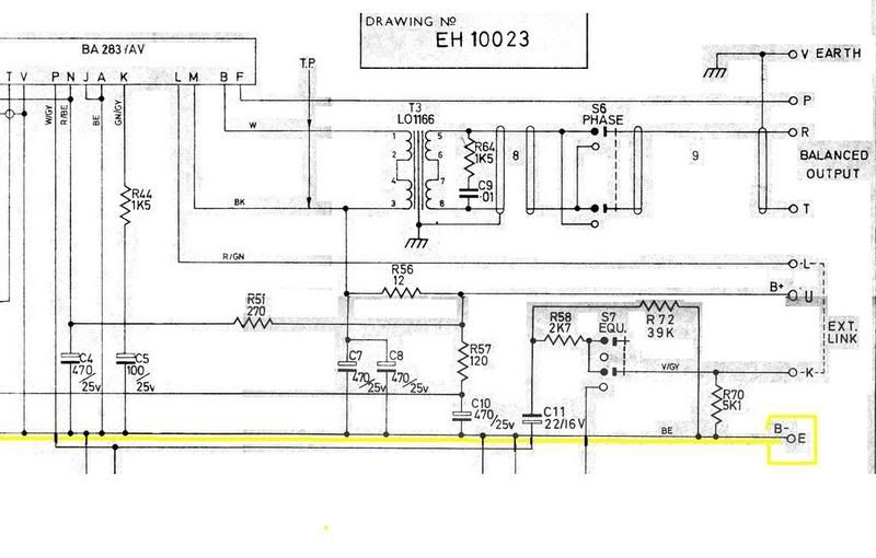
On the EH10023 drawing, ignoring all the switch pole part, there are a few hollow dot connection points scattered throughout the circuit. Most are numbered.

Are these going to a connector? I'm just curious as to why they are not solid dots like the other connection points.

Thanks

jim
 
Hi,

Just came across this thread. Interesting.

Just FYI I have made a complete and working unit based on the consolidated boards that I posted . I think it's a bit rough though to criticise layouts and boards when it's been posted free for the benefit of DIY. I mean, if you want rock-solid layouts, then pay for someone to design and build one (and believe me, it would cost a fortune and you'd be better off buying an original).

But anyway. I have tested the circuits and everything works. I had one small issue with a trace on the switching board, but I can pretty much guarantee that the rest of the board is solid. If people really want, I can post photos of the working unit (it's sitting behind me). Note that I'm talking about the consolidated board, rather than the individual boards that were based loosely on the original circuit.

As I said on another thread, I use this box on every single session I do, it sounds amazing.

Cheers

Chris
 
Chris, I think what they are trying to do is come up with a final correctly documented set of layouts for future builds. There are many layouts out there with errors.

The way I read comments on your build is that it was just that..comments.

Its all for the greater good of this place.

I asked you some questions by the way on my thread. If you could answer some it would really help.
see bottom of this page http://www.groupdiy.com/index.php?topic=25269&start=30

Myself and 3nity are looking at designing a 1 board 1073. Your board is an inspiration and I will probably go with yours as my first 1073.

I hope the others will chime in here and let you know they appreciate your contributions. I know I do.

Its all good guys. (ok where is that peace symbol emoticon?) :wink:

jim
 
Chris.

let me first say its great to finally hear from your here at the forum.
It was very generous of you to donate your project to DIY and I have to believe it took some serious hours of work to complete the project. I'm also glad you have returned to report that the layout does work well. Usually when I see a free layout I have to be cautious and a little skeptical for obvious reasons. I can't imagine the thought of buying all the parts to make a 1073 and then discover its not really what I expected. But on the other hand , it could be really satisfying as you have stated. So this thread is sort of a base for clearing up all the un-answered questions that never really get much attention or circulation, yet still remain important when attempting a project like the 1073 and other related complexities.
I think its obvious that your name appears here because you did something rather unique and have stirred up a lot of curiosity for DIY.
But I would'nt jump to the conclusion that I'm being rough to criticise your 1073. On the contrary, I was just venting some frustration because after visiting your website dozens of times over the past few years I never saw the information updated on the fixes. And I'm partially at fault for not contacting you directly. Especially the section where you mentioned
There are one or two minor errors, if anyone actually makes this and can't figure them out I will help you. It is a couple of traces and a couple of jumpers that need fixing.
So let me be the first to drop the question here on this thread, What are the fixes ? Can you post a pic and explain the details about it ?

I really like your website and I hope to see it become more informative than it already is. (time permitting) :thumb:


Bluzzi :

I have a question maybe someone can clarify for me.

On the EH10023 drawing, ignoring all the switch pole part, there are a few hollow dot connection points scattered throughout the circuit. Most are numbered.

Are these going to a connector? I'm just curious as to why they are not solid dots like the other connection points.

I think I know what your talking about, but can you post the EH10023 diagram and circle the areas of the diagram in question . this way everyone can see it and if I cannot answer the question someone else will have a chance to clear up the grey areas. this will also give others with the same question and chance to understand it as well.

There are no dumb questions here on this thread no matter how simple or complex.
 
Hi,

No problems. Funnily enough I used to DIY alot but now that I do the recording thing full-time I can't really do it much anymore. I'm constantly amazed at how big the DIY thing is now, I seriously recall having an email conversation with Kev back in 2003 discussing starting the DIY forum at recording.org.

Anyway. I guess I must shoulder some blame for not updating the website - I just honestly thought no-one would attempt to build one (the drawings alone took over 80 hours as I had no originals, only schematics). I found pictures of 1073 boards on the web and re-drew them in freehand.

I'm very close to opening up the box I made and taking some close-up photos of everything. The error was very minor (as I kept saying) and one quick look and I'd find it. In fact, I'll try and do it tonight and post it back up. I don't think it affects the boards as it's probably easier to just make them as-is and fix the wayward trace.

To help things along, I still have my parts lists that I made up in Excel.

http://www.linear-recording.com.au/neve/1073_parts_list.xls

It has prices (in $AU) as well as sizes, farnell part numbers and some alternatives.

But it's all good, sorry for being a bit knarky before. As I've said, I'd really like to have another one as it's a fantastic and useful piece of gear. So if anyone else is keen I'll be more than happy to be involved.

Cheers!

Chris
 
Maxwall Codered i just sent you the 6 new pcbs layouts reduced sizes.
waiting for your comments before launch the batch....

Chriss . your site was a great help when i start thinking diy a 1084...
audioforge
 
Shielding.jpg

Shielding2.jpg

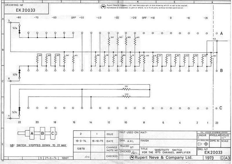
EK20033.jpg


In the EK20033 schematic ( Elma rotary switch ) the switch is set at -80db which is indicated by the capital letters A,B,C. If you were to look at drawing EH20023 (above illustration) the rotary switch is at a different position(-65db) which is indicated by the yellow path lines. The hollow circles (dots) appear to be shields ( one conductor wire with a shield around it). It may be there due to the length of the cable runs in the chassis. It also appears that the shields are joined at various points as well. Probably used to resist any stray noise or signal interferance to keep things quiet.
 
Thats what I thought at first but shoudn't the shield then go to ground points?
I don't see that happening.

Anyone else have any opinions on this?

jim
 
Bluzzi

look again the shields are tied to a B- rail at points ' V & T ' on the 284 and 283 cards above it.
 
Sorry to dig up this old thread, but I have some comments about the 211 boards.  It seems there are 2 versions, the 211 and the 211A.  From what I can determine, the 211 board was used in the 1073 module, and has a 2k7 resistor from the amp input to the top of the inductors.  There is no “P” terminal either.  This resistor seems to set the Q of the LC circuit.  In the 211A board (which is in the 1084), that same resistor has a value of 6k8, and has the “P” terminal that goes to the “Hi Q” switch.  What the “Hi Q” switch does is to connect a 7k5 resistor in parallel with the 6k8, resulting in a resistance of  3k57 ohms when in the “Hi Q” position.  What I have measured is that the Q of the 1073 is actually higher than the 1084 with the “Hi Q” switch engaged.  The Q of the 1084 is much lower than the 1073 with the switch disengaged, so the “Presence” bands in the 1084 are much broader with the “Hi Q” switch out.  Seems like they should have labeled this switch “Lo Q” when disengaged.  Do folks prefer the lo Q of the 1084 to the 1073?
Best,
Bruno2000
 
i'm going to continue digging up this old thread - 'cause it has some great info...

Bruno2000 - interesting questions - i can't find anyone on the net discussing the actual Q differences of the mid band on the 1084 vs 1073 - only that the "1084 is better 'cause it has the high-q switch".

kinda reminds me of spinal tap - "yeah, but this one goes to 11"  ;D

personally, i think i'm going to go with the 6k8 resistor on my EQN being that it's a 1084 derived circuit with two settings of Q.
 
electrochronic said:
Shielding.jpg

Shielding2.jpg

EK20033.jpg


In the EK20033 schematic ( Elma rotary switch ) the switch is set at -80db which is indicated by the capital letters A,B,C. If you were to look at drawing EH20023 (above illustration)  the rotary switch is at a different position(-65db) which is indicated by the yellow path lines. The hollow circles (dots) appear to be shields ( one conductor wire with a shield around it). It may be there due to the length of the cable runs in the chassis. It also appears that the shields are joined at various points as well. Probably used to resist any stray noise or signal interferance to keep things quiet.

any chance for an images  "reup" ?
cheers
 
Back
Top