sonolink
Well-known member
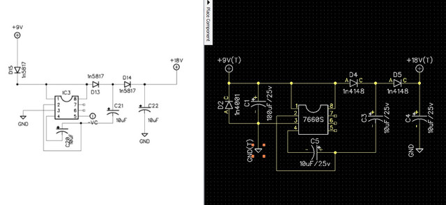
The 2 attached circuits are supposed to be the same, but the one on the right has an extra cap and a diode in the opposite direction. Can someone explain the reason why and if there is a "correct" one please?
Thanks
Cheers
Sono
Thanks
Cheers
Sono
")