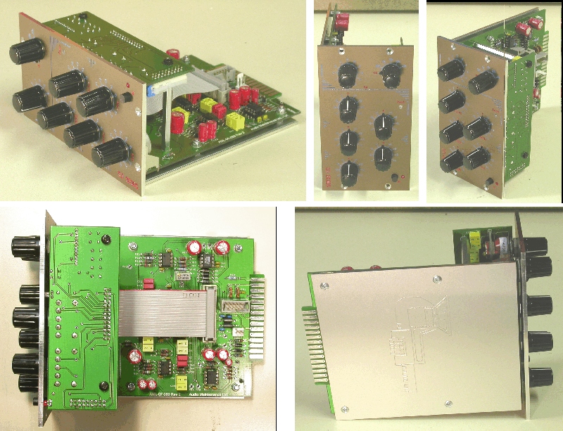
3D "AIR" EQ - "Night EQ" PCB's Complete!

GroupDIY Audio Forum

Help Support GroupDIY Audio Forum:

This site may earn a commission from merchant affiliate links, including eBay, Amazon, and others.
OK, it's done!  8)
It works like a charm (already did but now with stepped switches, hard bypass, new knobs and a new frontpanel.

nite1.jpg

nite2.jpg

nite3.jpg

nite4.jpg
 
Autophase said:
Yes I have seen the resistor tables, ill probably do the same as harpo and have 5x 1db steps each way.

Would anyone be able to clarify another thing for me please, i spent the afternoon reading most of this thread. To my understanding of stepped attenuators, each resistor goes a a lug on the switch then the other resistor leg goes to a common point, usually a ring or the same trace on some stripboard.
But I have seen in this thread some people wire the attenuator in series, so each step increase introduces another series resistor into the signal path, my concern with the series method is that it introduces more noise with each additional resistor in the signal path.

please can you clarifiy which is the correct / most accrate method for this eq? If I am missing something please fill me in, afterall the building is only half the reason I am here, the other half is to learn (and hopefully help someone else in the future)  ;D

sorry for bump, but I could do with some assistance on this please  :)

Hi Guys, if anyone could give me a bit more guidence with the stepped switches that would be much appreciated.
 
Hi Guys
sorry to ask the same question again, but this thread seems to have been inactive for a while, if anyone with experience of this EQ can help me that would be much appreciated

"I have seen the resistor tables, ill probably do the same as harpo and have 5x 1db steps each way.

Would anyone be able to clarify another thing for me please, i spent the afternoon reading most of this thread. To my understanding of stepped attenuators, each resistor goes a a lug on the switch then the other resistor leg goes to a common point, usually a ring or the same trace on some stripboard.
But I have seen in this thread some people wire the attenuator in series, so each step increase introduces another series resistor into the signal path, my concern with the series method is that it introduces more noise with each additional resistor in the signal path.

please can you clarifiy which is the correct / most accrate method for this eq? If I am missing something please fill me in, afterall the building is only half the reason I am here, the other half is to learn (and hopefully help someone else in the future) "

sorry for bump, but I could do with some assistance on this please 
 
I'm probably not the best to answer but I would say series would be fine. Most of the guys here build there stepped controls in series and don't have a problem. Plus they're probably the cheapest method for stepped controls too. :)
 
hi guys, this thread seems to have been left by the way side, can anyone who has built one of these or knows anything about it help me out at all?
I have a pari of stuffed boards and a PSU, I just need some help with the atenuators.
I want to use them in stereo for mastering and I was wondering if I could use these http://glass-ware.stores.yahoo.net/a5stat.html
it seems they would be set up with one knob controlling, 1db incriments and the second controlling minor incribments 1/6th db + or - in this case, i would obviously need a pair of knobs for each band, but I dont mind that so much.
Please let me know if you think this is possible.
 
Autophase said:
.., I just need some help with the atenuators.
None of the pots in this EQ is an attenuator. These rheostats set the amount of gain for the following summing stage.

I want to use them in stereo for mastering and I was wondering if I could use these http://glass-ware.stores.yahoo.net/a5stat.html
it seems they would be set up with one knob controlling, 1db incriments and the second controlling minor incribments 1/6th db + or - in this case, i would obviously need a pair of knobs for each band, but I dont mind that so much.
Please let me know if you think this is possible.
I wouldn't do it, but with a little redesign and some math to catch the then lawbending input resistors now in parallel to the shunt arm resistors of your attenuators, it seems possible.
 
Slenderchap said:
Just "for a laugh" I put the Nite EQ in a 500 series module last year;

5003d_overview.jpg


Faceplate looks like this;
http://www.audiomaintenance.com/downloads/5003d_front.jpg

and I even did a transformer output option PCB;
http://www.audiomaintenance.com/downloads/5003d_eq_transformer_option.jpg

It worked just fine, but slightly differently from the original in that when you boost a band it brings the "out of band" level down as well so it makes it difficult to overload (consequently the "Sub" band has the effect that the signal gets quieter when you increase the level..... because the "out of band" is basically every thing audible)...

There was one very small error on the PCB which I have now corrected.... but did not get any made.... I was thinking about getting a few boards made and then sending the gerbers to Gustav.....

... does anyone want these ?

Colin
www.audiomaintenance.com

FYI:I added these to the shop https://pcbgrinder.com/index.php?route=product/product&path=59_80&product_id=87
 
Gustav, do you have any plans to offer this EQ in traditional format? Or is it easy enough to convert this for use in a standard 19" module?

Thanks, Geotone
 
geotone said:
Gustav, do you have any plans to offer this EQ in traditional format? Or is it easy enough to convert this for use in a standard 19" module?

Thanks, Geotone

I have to admit, I have never built a single thing in 500 series format og even looked at a 500 series frame, but I don't see why you shouldn't be able to do that unless theres some esoteric, theoretical barrier I didn't think of. http://www.lunchboxhero.com/resources/docs/tek/api_pinout.jpg

And to avoid soldering directly to the gold fingers..
http://www.sonicworld.eu/Vintage-Gear/Connectors/Connectors-for-Vintage-Modules/305-Female-connector-for-API-500-Serie-Modules-used

Maybe I should stock a few of those female connectors.

Gustav
 
I was contemplating on the concept of having rotary switch change values only in one direction and an additional toggle switch to choose if it will cut or boost. Came up maybe with a solution but I still need verification.

I went from the assumption that rev log pots use 90% of their values on one side of the rotation. So if we take 500K pot and divide it into plus and minus sections (boost and cut) it would be left half (CCW to center) with total value of 450K and right half (center to CW) with 50K. In this arrangement used in EQ-3D filter sections maximum cut would be equal to maximum resistance (450K+50K), center would be 50K resistance and maximum boost would be zero ohm.

From that point I went to draw an ideal schematic that would use 2 throw switch (more expensive solution).
This would be easy since different resistor series could be used for boost and cut.
If it was cutting, switch total resistance would be 450K + fixed 50K.
In the boost position it would be the same series resistance on the switch 450K but paralleled with 56K2 resistor to have it range from zero to 50K.

My next task was to come up with a way of using only one rotary with 1 pole in either boost or cut. The complicated thing here is that boost and cut would end up in different orientation - minimum for boost would be maximum for cut and vice versa.

So I came up with this schematic attached here to overcome that problem - Could someone check if this will work.

Rotary switch resistors would probably have to be linear scaled - probably 450K divided to 11 if using Lorlin 12P1T = 40K each. Or in reality 39K with modified values for fixed resistors to keep the total resistances stable. Or even some other value if targeting different boost/cut amount.

I suck in simulation software so I was unable to sim this schematic to see what would it show!

Please comment!
:)
 

Attachments

  • 16052013119.jpg
    16052013119.jpg
    91.8 KB
Have just completed my unit and am wondering whether others also see the frequency response plot I am getting.

The attached file is a Fireface 800<->NightEQ left channel loopback (Out to In to Out to In) and my attempt at getting flat response when the EQ is engaged.

Am getting about -1db drop at 75Hz, -0.4 at 310Hz and -0.2 at 1.8KHz no matter how I try to zero it.
Both left and right channels exhibit a very similar curve.

Are others getting a similar response?
 

Attachments

  • Nite EQ.jpg
    Nite EQ.jpg
    129.1 KB
dagoose said:
why not use a 2 deck switch, one deck for boosting, one deck for cutting and use a switch to switch between both sides of the switch? I think that will be way more simple.

Yes, that was my first idea!
But then I was puzzled if it could be done with only one deck so I came up with this.
I haven't tested it but in theory I think it should work.
:)
 
shot said:
I was contemplating on the concept of having rotary switch change values only in one direction and an additional toggle switch to choose if it will cut or boost. Came up maybe with a solution but I still need verification.

I went from the assumption that rev log pots use 90% of their values on one side of the rotation. So if we take 500K pot and divide it into plus and minus sections (boost and cut) it would be left half (CCW to center) with total value of 450K and right half (center to CW) with 50K. In this arrangement used in EQ-3D filter sections maximum cut would be equal to maximum resistance (450K+50K), center would be 50K resistance and maximum boost would be zero ohm.
Cut (CCW direction) would be between 500K and 50K. Boost (CW direction) would be between 50K and zero. Add the 5K62 fixed series resistance on top. Voltage gain is set by R30/(pot value + fixed seriesR), IE between 56200/(0+5620)=10 and 56200/(500000+5620)=0.111 or in dB between LOG(10)*20=+20dB and LOG(0.111)*20=-19.1dB per bandwidth limited gain stage feed and an R24/(R24+R25) attenuator in front. 

So I came up with this schematic attached here to overcome that problem - Could someone check if this will work.
Will work, but I'm sure you won't like it, switching from min.cut to max.boost in CCW position and vice versa, so two additional switch poles would at least connect the rotary switch upside down and your law bending 56K2 when switched to boost will give you 9 steps for a total of 2dB boost and 14.25dB in the last (from your pic the 1st.) step.

Rotary switch resistors would probably have to be linear scaled
probably not ...

I suck in simulation software so I was unable to sim this schematic to see what would it show!
Just fill in your switched resistor values in previous formula to get an idea what the result might be.
 
You're right Harpo!
Now I see my mistakes.
Thanks for your help!

I have to travel for few days on gigs and when I come back I'll look into it more.

I don't have problem using two pole switch but it's kinda intriguing for me to explore and contemplate more on this one pole design. You gave me a good food for thought now!  :)

And btw, I'm really impressed on the pot tweaking documents you did. Wow! Respect!
 
whomper said:
Am getting about -1db drop at 75Hz, -0.4 at 310Hz and -0.2 at 1.8KHz no matter how I try to zero it.
Reason for your response curve is, these bands are not filters but bandwidth limited gain stages. Center frequency of each band has to be exactly 2 oct. = factor 4 apart, so the -6dB/oct. slope adds up to unity gain with its neighbouring gain stage. If FI for the typo '650Hz' band (should be 640Hz) you have fitted 120R and 1K2 resistors instead of from schematic 127R and 1K27 resistors (ideal value would be 124.3R and 1K243 with perfect 2uF and 200nF caps, if neighbouring lower stage would be set for 160Hz for real instead of 156Hz), this frequency band will rise from 627Hz to 663Hz, giving your shown dip at 321Hz for this example value.
 
Harpo said:
Reason for your response curve is, these bands are not filters but bandwidth limited gain stages. Center frequency of each band has to be exactly 2 oct. = factor 4 apart, so the -6dB/oct. slope adds up to unity gain with its neighbouring gain stage. If FI for the typo '650Hz' band (should be 640Hz) you have fitted 120R and 1K2 resistors instead of from schematic 127R and 1K27 resistors (ideal value would be 124.3R and 1K243 with perfect 2uF and 200nF caps, if neighbouring lower stage would be set for 160Hz for real instead of 156Hz), this frequency band will rise from 627Hz to 663Hz, giving your shown dip at 321Hz for this example value.

Harpo, thanks for the elaborated explanation. Think I have chosen the 120R/1K2 combo.

Looking at the response curve I am getting, might it be that the Q factor is a little too narrow? Even if I will move the 650Hz around a little, I am not sure it will level the 350Hz dip I am getting.
 
whomper said:
Looking at the response curve I am getting, might it be that the Q factor is a little too narrow? Even if I will move the 650Hz around a little, I am not sure it will level the 350Hz dip I am getting.
With correct distance between these bands they will add up to a flat response and you won't change the fixed -6dB/oct slope.
You might adjust resistor values (seems easier than adjusting the 1uF or 100nF cap values) in a way, this 1/(2PI()*R*C) for the HPF and LPF setting in the lower 4 bands is exactly factor 4=2 oct. apart from its neighbouring band, IE 10Hz, 40Hz, 160Hz, 640Hz. Reason there are always 2 caps in parallel in these bandwidth limited gain stages is, to get statistically closer to the ideal caps value because parts come with tolerances that might cancel out by this paralleling (for example: ideal caps value 1uF||1uF=2uF; real world caps are maybe 0.974uF||1.030uF=2.004uF).
 

Latest posts

Back
Top