47-styled microphone build thread

GroupDIY Audio Forum

Help Support GroupDIY Audio Forum:

This site may earn a commission from merchant affiliate links, including eBay, Amazon, and others.
In addition to head amp noise comparisons, using the only other mic I had sitting around with a removable capsule--a lowly Oktava MC-012 (modded), I did some comparisons of the unwanted microphony of head amps just for the hell of it.  I put a 'dummy capsule head' on the Oktava to complete the shielding of the head amp, and ran some comparisons.

interestingly, this solid-state mic's head amp is far more microphonic than the 47-inspired tube mic I built.  With it plugged into the J99 full up, I had no problem clipping the converter by rapping on the mic's body with a fingernail-- even with just light tapping.  I found this interesting (and a little surprising).
 
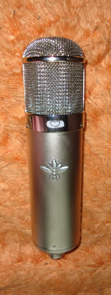
It mildly bothered me that my mic didn't have a badge where the original Neumann badge went.  Looks too plain for my tastes without something there.

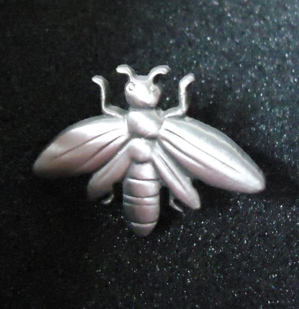
So I got creative.  I found for a couple of bucks each online an 'antique silver' lapel pin that looked like a bee.  My name starts with "B" so I guess you could make it a play on my initial if you wanted, but in reality I just thought it was the coolest looking pin they had.  I bought two.

DSC00852.jpg


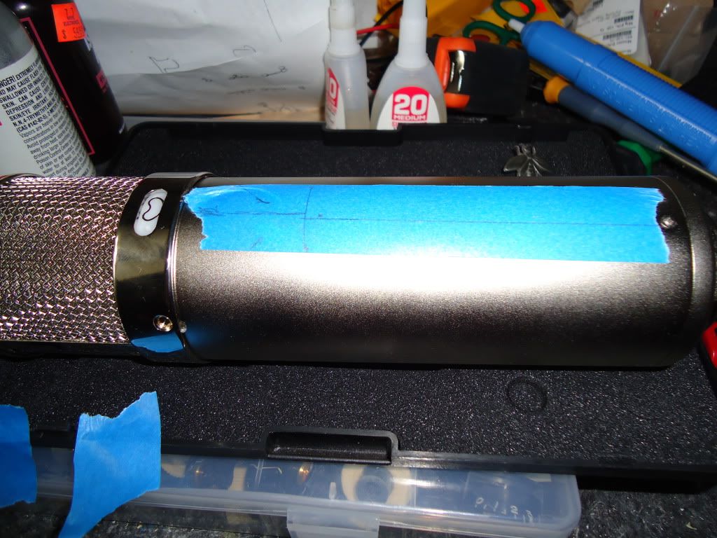
For whatever reason, the pattern selector switch cutout is slightly off-center with respect to the two headbasket screw holes it resides between (and with the body attachment screw near the base of the mic).  Being aware of this, I measured and marked a location to split the difference so nothing would look too ill-aligned with respect to my cool bee.

DSC00853.jpg


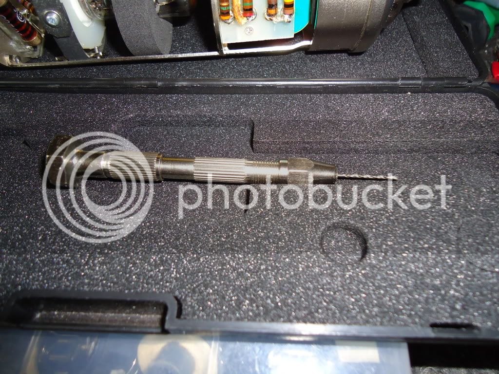
Using a micrometer, I measured the lapel pin's post.  Then I selected a wire gauge drill bit the same size.  I put the wire gauge bit into a small pin vise.  I want to drill this hole by hand-- the mic body is too nice (and expensive) to screw up, so I only get one try.

DSC00854.jpg


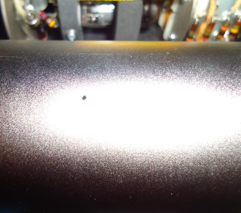
I left the blue tape on to avoid marring.  It came out pretty good.

DSC00855.jpg


Using wire cutters to cut the post off short, I put the pin in the mic (it required just a bit of resistance to push the post into the hole, which is what I wanted).  One thing I didn't plan for-- the post had a bit of a flange near the top.  My options were: 1) drill a bigger hole for the flange, or try to countersink the hole somehow; 2) file the entire post off and use cyanoacrylate glue to hold the pin to the mic body; or 3) allow the pin to be stood-off the mic a bit, securing it with CA glue.  I chose 3 for now-- I could always do one of the other two if the pin interferes with the shockmount, case, or proves to be too unstable.  It actually looks really cool stood-off the mic a bit.  Very dimensional and slick looking, so I hope it works.

DSC00856.jpg


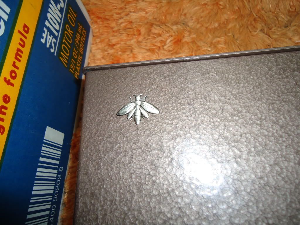
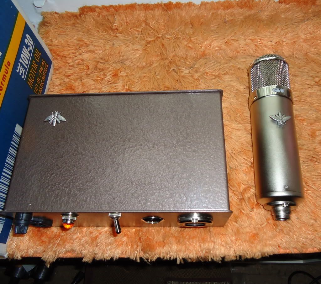
I had bought an extra pin in case I screwed up the first.  Well, I didn't, so I took that opportunity to drill a bigger hole in the PSU case, file off most of the post, and use CA glue to attach it, completing the 'set'.

DSC00857.jpg


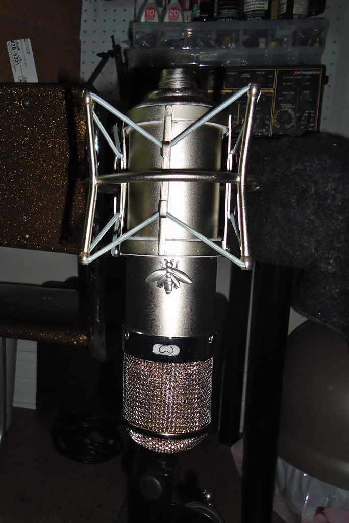
Here you can see the added dimension of the stood-off insect pin.

DSC00859.jpg


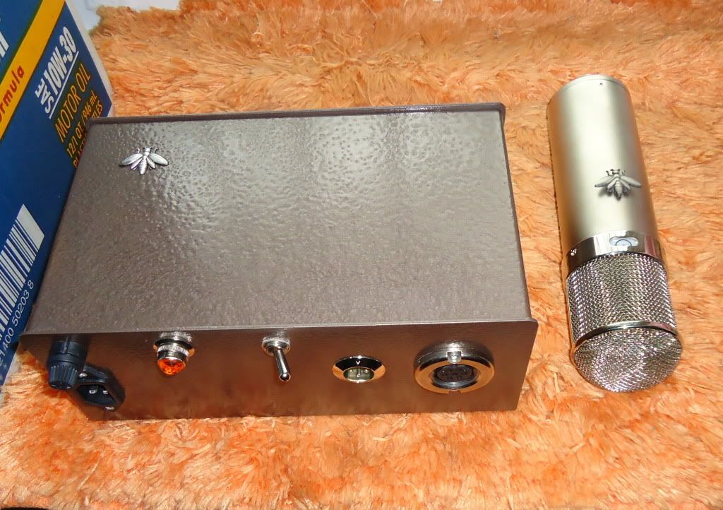
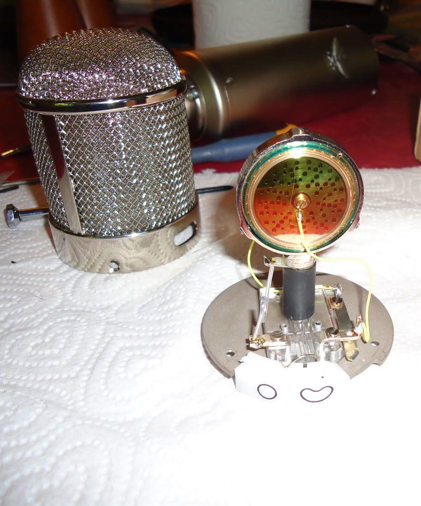
Since this mic will have an old-school PVC diaphragm it will spend most of its life hung upside-down to protect the diaphragm from the tube's heat.  As such, I positioned the insects so they'd both be pointing the same way with the mic in its most typical position. 

DSC00860.jpg


Now it doesn't look quite so naked.  A couple more weeks until my capsule arrives.  It better get here soon, or I'll have the whole mic bedazzled, frocked, and decoupaged by the time it gets here.
 
Thiersch capsule arrived today and I finished putting the mic together. First, a piece of solid silver wire, teflon insulated, to electrically connect the backplate via the capsule mount

DSC00868.jpg


Ready to accept the capsule now...

DSC00871.jpg


Very carefully, I secured the capsule to the capsule mount with three threaded set screws, taking care to neither touch the membrane, nor puncture it with an errant screwdriver. 

DSC01050.jpg


In order to solder the capsule's lead-out wires, I first want to protect the capsule membrane itself from errant splashes of solder or flux.  To do this, I modified a piece of packing material to create a little plastic pouch to slip over the capsule itself during soldering.

DSC01051.jpg


All soldered up and ready to go.

DSC01052.jpg


DSC01054.jpg


I also connected the EF800 shield (pin 6) to ground.

Listening test is very impressive in the timbre of sound captured by the microphone.  Incredibly beautiful.  However, I have a slight hum issue that I suspect is attributable to my power supply design or layout.  This is a bummer for me.  Now it's time to sit down and see if I can figure out where I went wrong, and see if I can improve this power supply, or if I must scrap it and start all over with a new one.

 
With all the care you put into the build, I can appreciate your frustration.  Are you sure it's the P/S?  Disconnect the mic.  If you still hear the hum with just the P/S on, you've at least isolated it as the culprit for sure. 
 
I can change the hum by varying the location of grounds in the PSU.  Also, the mic is a proven schematic/design, and I'm confident it's built correctly.  This is why I feel certain the issue is the power supply.

I've disconnected all of my grounds and gotten a bunch of clip leads out trying to figure out the quietest way to connect the grounds, physically.  I haven't gotten very far.  I've gotten varying degrees of better/worse, and even one or two that are "almost acceptable but not quite."

Basically, I don't know anything about physically laying out grounds.  I don't know what should be grouped together and what should be kept separate.  Trying to tie everything together to one star ground didn't work well at all.  I'm taking a break for the night.
 
I got this hum problem sorted out!  :)

What I ended up arriving at (through experimentation) was to have two star grounds.  One was at the first filter cap for the filament supply and included all filament supply grounds.  The other was at the first filter cap for the high tension supply and included all high tension supply grounds.  These two star grounds then connect together (and to the chassis) at  the 7-pin mic cable jack.  The AC safety ground from the wall is connected with a very short wire to the opposite side of the chassis.

I don't have an anechoic chamber in which to test the system's noise floor, but even with the mic as well-isolated from sound as possible, a short recording reveals the noise of the system to below the noise floor of the room to the extent that I have a hard time separating it out when listening in headphones.  I'd say "mission accomplished" until a more demanding (quiet) environment reveals otherwise.
 
Thanks!  I've been messing around with this mic today and it's absolutely outstanding.  It exceeds my expectations going in.  Couldn't be happier.
 
Thanks everyone. Just as a little test after finishing it yesterday, I put it up in my mostly-untreated room, sat about 2 feet away from it, and played/sang an old James Carr song. I'll be damned if (the vocal 'talent' notwithstanding) it isn't a perfectly good-sounding capture of the guitar and vocal. I was sittin down, the mic was about at 'guitar level' angled up toward my head and about 2 feet back... maybe a little closer. 

Apologies to James Carr, Steve Cropper, and everyone else!

http://www.soundsdifferent.com/music/Mic_Test.wav

I used a seventh circle J99 into a Lynx Aurora, and if you listen closely, you can hear the hum of my refrigerator in the background... not exactly a 'scientific test,' but this is just the raw 24/48 track-- no processing of any kind.

I'm encouraged by the timbre, and the 'space' around everything--even for just a single mono source.  Imagine if I placed it carefully in a good room on something really worth recording!  All-in-all, a worthwhile project.
 
bockaudio said:
so the simple, choke fed psu is quiet?

I don't have an anechoic chamber, but it's below the noise floor of any room I have.  Not necessarily saying a whole lot, but once I got the grounding right, it seems pretty quiet to me. I had a hum issue at first, but then I figured out I needed a dual star-ground scheme with the filament and dual-choke high voltage supplies each needing their own star ground, both of which were then tied together and tied to the chassis at the mic cable jack.  Until a more demanding environment proves otherwise, it seems quiet to me.
 
hello to everyone!
i know that this topic is old,but i want to try to make a question here.
I trying to do the same project.a u47 based in the schematic of AMI with a telefunken ef800.But i´ve got a problem…
where i find a PSU schematic for this project in particular?
and the second question,How do you do the grounding section to cancelate the hum?
Thank you very,very much
 
Back
Top