8 Channel, 3U NEVE 1073 completed

GroupDIY Audio Forum

Help Support GroupDIY Audio Forum:

This site may earn a commission from merchant affiliate links, including eBay, Amazon, and others.
statzern said:
you will not be able to get your +48 up to 48. And probably will have issues with your +24 too.

I dont think this is true. The AC/DC has a voltage doubler, no?

Perhaps you had a problem with the amp rating of your transformer?

 
I finished up my first channel today and tried it out, I'm getting sounds but also getting crazy hum. I haven't mounted anything to my chassis yet but I think the hum may be coming from my power supply. I don't have an oscilloscope but I used my DVM to measure the +24 rail and I had it check for Hz on that rail and it reads 60Hz. I'm using a left over SSL 9k PSU board. I tried upping the caps to 2200uf but that didn't help, I feel I may not be getting full wave rectification, any help guys?
 
When i had mine outside of case etc...i had to put ground wires running all over the place, but it was quiet.


Hey guys, let me explain what I am trying to say:

In Martin's Assembly Guide, he suggests the Amveco TE62085 power transformer. This transformer will give you 22 VAC if you wire it in PARALLEL, but Martin's guide is set up to be wired in SERIES which will give you a total of 44 VAC. If you look at the datasheet (http://www.amveco.com/pdf/Amveco_Catalog.pdf#page=25) you will see that wiring the output AC across the GREEN and BLUE wires is putting the secondary windings in series.

Anyway, it definitely wasn't a problem with the current capacity of my transformer - it was like 100VA for only 2 channels!

Hope everyone's enjoying their preamps, I definitely am! Unfortunately, medical school has gotten in the way for now.. so the recording has significantly slowed... I wonder if I'll ever have free time again??
 
Hi Martin,
I really love the way the schematic diagram looks in your "EZ1290 Assembly Guide".
Which software did you use ?
 
There is something that I really like in Martin's drawing, maybe in the components proportions.
But looking closer, it seems it has been done manually with a simple draw program.
All the merit goes to the artist.
 
I have a question that I think has been touched on a bit in this thread, but I can't figure out a definitive answer.

One of the standoff (mounting holes) connects with 0v on the pcb. Now if I use a metal standoff wouldn't that connect 0v and chassis ground together?? Which is a no no when it comes to grounding?? Am I meant to use a plastic standoff? Am i meant to connect to chassis ground here also via another 10r resistor as well as the one in the PSU?
Now I understand the 10r in the PSU, and even though I'm not using the JLM acdc board, I know how to implement it into my own PSU, but it's more the use of this standoff thats confusing me. If we're meant to use plastic standoffs then why is 0v even connected to the mounting hole?

desol asked a similar question earlier in the thread, but I'm not sure if there was an answer. If there was I missed it somehow, but that can happen when reading through long threads.............. just try the G1176 one ha ha
desol said:
Hey Martin,

Just wondering, what is the purpose of connecting the one mounting hole in the driver stage to 0v?
Is the shielding plate on the back supposed to connect to this mounting hole? I guess it would even if using plastic standoffs, as the screw and nut still make contact? I was thinking the shielding plates should go to ground? Hmm..

 
I have heard people say dont use metal standoff's.... but in my build I DID have to connect that PCB ground to chassis.

When I rebuilt mine to tidy wring and fix a few other probs, I decided to use a metal M4 bolt to ground to chassis and it works well, and means you dont have a messy wire.

I went for a bolt ratrher than standoff, because I glue my standoffs, and then there would be no continuity between ground and case. Metal standoff and little screw through bottom should work though.
 
hi guys...

i was just using my 1290s for the first time in a while. all seemed good, then suddenly the 47r near the 2n3055 started to smoke.

i only used a 1/2 watt here, but thats as per the bom and should be ok according to martin.

any idea what might cause this resistor to burn?

thanks a lot]
jake
 
....also, the phantom power led indicator was flickering. I find this weird as surely that is unrelated to the pcb? only thing they share is the 0v.

Cheers
 
Hi Jake,

Burning the 47R is most likely due to improper biasing. Do you get 22.66 volts on TR3 casing? What are you using for PSU? The excessive current drain on the +24 rail could make the +48 flicker depending on what PSU you use.

M.
 
cheers martin,

I was getting 22.8, but have now adjusted to 22.6... the smokey channel still seems to work fine, but I will swap out the resistor when I get a chance.

The unit seems to be stable on its own, but when im using a pad to use line signals and patching it around. I cant understand whats happening but its something weird. I think im going to take it out of my patchbay and just route the outs manually.

Thanks for your advice, its really appreciated as always  :)

BTW - im using the JLM AD/DC - there was some debate on wether or not the toroid should be wired in series or parallel... can you advise?

Cheers!
jake
 
Hi everyone, Hi Madriaanse. Just amazing work, congrats.

I'm a completely newbie and I was searching a nice 2 channel pres project to start my lab when I found this. Looks like the holy grial for me since I love Neve sound. But, after following about 10 pages of discussion I get dizzied with many versions of assembly instructions, BOMs, ideas, etc. . . and there was about 22 more pages to go.

So here I need some orientation.
Is this a recommended project for a DIY'er with only DC circuits experience and just AC basic understanding but no practice?
If so, can anybody point the latest versions of the documentation (or more suitable) for a 2 channel version?
What's the best power supply option? (I will connect it on 110V)
What is the approximated total cost for a 2 channel version? . . .and for a 4 channel?

But if not, what project would you suggest to start over? (I desperately need some new pres).

Thanks!


I'm a newbie too and made this pre as 1st project : it is very easy to built, worked at the 1st time ! For the PSU I took a JLM Audio (very good and easy too) but the FiveFish Audio look awesome too !
I suggest you to patiently read the entire threads (the 2 of madiaanse) and wrote somewhere everything that might be important, the different issues of the builders and how they fixed them... That's what I did for all the projects I've done, this way when I begin to solder I know exactly what I do and how to avoid issues. Be patient, take your time and everything will be ok. Plus, everyone would help you here if you need.

Best,
Ben.
 
a lot of your questions are answered in the FAQ's at the begining of this thread. as evil cat says, read them, then read the entire discussion.

This is theoretically an easyish build, but there is perhaps a little more offboard wiring than some other projects, as transformers  are not pcb mounted.

This isnt difficult, but is a little fiddly, and consideration needs to be given to transformer placing in the early stages (as per martins suggestions).

I had quite a lot of issues with my build, but some was down to bad luck (faulty open circuit carnhills), some was due to to stupidity and some were just the normal kind of faults you have to troubleshoot an anything like this.

 
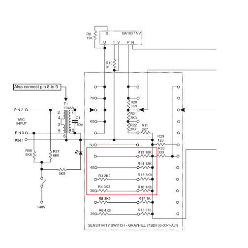
I am getting some weird behaviour from one of my EZ1290 channels. some of the resistors that make up the voltage dividers on the input switch appear to have changed their values  ???
I started getting weird level steps for positions 3-6 of the grayhill switch and when I measured R3, R4 and R13-16, all the values were off. This is with the input switch set to 75db so none of these resistors should be connected to anything (apart from R13-16 which have one side connected to ground). How is this possible? Faulty Grayhill switch?
inputswitch.gif

ETA: solved...solderbridges on the grayhill switch :-[
 
I haven't had the moment to go through all 32 pages... is there a PDF version of the BOM available? I can't open XLS on the Mac.

Thanks!
 
Back
Top