8 Channel, 3U NEVE 1073 completed

GroupDIY Audio Forum

Help Support GroupDIY Audio Forum:

This site may earn a commission from merchant affiliate links, including eBay, Amazon, and others.
desol said:
Sry...i kinda feel bad, in this case....cause i re-read your previous messages...and it does sound like you are helping yourself. There's been so many people tho....that just expect everything handed easily to them. I read hundreds of pages of thread info when i started my first build like, 5 years ago. No easy way out.

Quick search on the forum yields: http://www.groupdiy.com/index.php?topic=35422.0

That blue seems pretty decent, although it's only a two channel unit. Dan could definately do something custom.

Don't worry, you are right. I have almost done the PCB, I am waiting for the Grayhill switch and some caps. I have ordered the case from Collective Case, its the gray one but that will do :). I have ordered some VanDamme cable for the internal wiring. I also have ordered the PowerPlant Kit PSU from JMLAudio and the Go Beetween kit. I have to wait next month for the transformer and I that will be it. I am excited !
Thanks all of you on this forum and Martin of course. It's a great project.
 
indiehouse Recording said:
Yep, sure enough there's a 10R on the Power Plant. Thanks again!

as a bonus to checking the BOM you can also measure the circuit when it's built and look for the 10ohms resistance between the chassis ground and audio ground. just to be sure.
 
The electronics store in my town carries 4 conductor shielded wire (for power cable between PSU and Pre's). The BOM recommends 18AWG, but the electronics store only has 22AWG.

I did a bit of research, and it seems that 22AWG is rated .92 amps for power transmission.

I'm using the JLM Power Plant kit. Will I be ok using 22AWG instead of 18AWG?
 
That amperage rating has to be wrong.

I'd ask the electronics store to order some in for you, with no additional charge.
 
sorry if this has been answered befor. i admit i have not read all 74 pages of the thread. i see that the stand offs for the 2n3055  should be non conductive. but the screws that hold it to the pcb are threaded through two large pads. if the screws are metalic and contact these pads the 2n3055 case is not going to be isolated. i see no mention of nylon screws and washers in any posts ive read. if the 2n3055 is not isolated why is it important to use non conductive spacers??
8) 8) 8) 8)
 
seavote said:
sorry if this has been answered befor. i admit i have not read all 74 pages of the thread. i see that the stand offs for the 2n3055  should be non conductive. but the screws that hold it to the pcb are threaded through two large pads. if the screws are metalic and contact these pads the 2n3055 case is not going to be isolated. i see no mention of nylon screws and washers in any posts ive read. if the 2n3055 is not isolated why is it important to use non conductive spacers??
8) 8) 8) 8)

From the Assembly Guide:

"The Spacer can be made by cutting a 3/8” 6-32 aluminum standoff in half. Digikey Part # 2209K-ND. Standoff must be metal (conductive)."

Hope that helps.
 
thanks. i misread this part of  madriasse s first post
"What type of standoffs (mounting pillars) should be used to mount the EZ1290 boards?

Any nonconductive (nylon) standoffs will work. Don't use metal (conductive)"
i see this is for the pcb not  the 2n3055
 
Hi all,

I've got another quick question (and I do really appreciate all the advice!). I'm drilling holes in the bottom of the case to mount the input/output tranny's. Do I need to drill for the standoff's? Meaning, do I need to affix the standoff's to the bottom of the case by means of a screw from the bottom through the case into the bottom of the standoff? Or are the standoff's meant to be "floating" and not attached to the bottom of the case?

 
there are different types of stand offs. depends on what your using. some are "self stick" and many forum members are ok with them. i prefer those that are screwed from the bottom of the case.
 
seavote said:
there are different types of stand offs. depends on what your using. some are "self stick" and many forum members are ok with them. i prefer those that are screwed from the bottom of the case.

I have the standoff's from the BOM. 6-32 threaded, I believe. So you are saying they should be affixed to the bottom of the case? I suspected as much, but wanted to be sure before I drill a bunch of holes.
 
PSA: I found some 18AWG, 3 conductor shielded wire for sale on eBay.

http://www.ebay.com/itm/18-3-Shielded-Wire-18-Gauge-3-Wire-Conductor-Choice-of-Length-/181002268832?pt=LH_DefaultDomain_0&var=&hash=item2a249370a0

Hope this is helpful to someone.
 
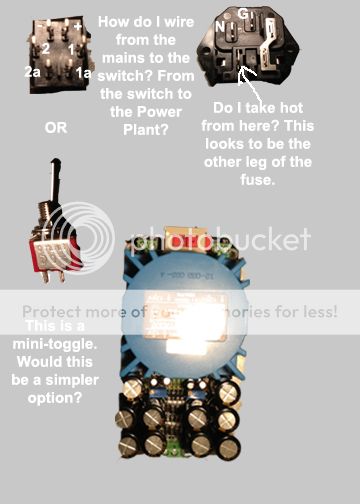
Sorry to trouble with another question, but I want to make sure I get this part right. I am currently trying to wire in my mains and rocker switch for the PSU. I am using a JLM Power Plant.

What I am trying to do is wire in a power switch. I have a lighted rocker switch (http://www.digikey.com/scripts/DkSearch/dksus.dll?WT.z_header=search_go&lang=en&keywords=360-1731-ND&x=10&y=19&cur=USD).

The switch is a DPST ON-OFF, rated 9A (AC), 125V. It has 6 legs on the back, and I'm confused as to how to go from the mains to the switch, then to the Power Plant. Also, do I need a resistor for the LED on this switch? The illumination voltage for the LED is rated 1.95VDC. Where would the resistor be wired in at?

I also wanted to mention that I used the continuity setting on my DMM to try to determine the legs that would open/close the circuit, and tried every combination with no success. This confused me.

I have a mini SPST, ON-OFF toggle rated 120V AC (http://www.mouser.com/ProductDetail/Mountain-Switch/108-0001-EVX/?qs=sGAEpiMZZMvudeGI7i40XJuO3OFUtqTEvJ%252b1OLTC0W8%3d).

Would that be easier?

One last question. The fuse is built into the mains input. I have marked the ground and neutral terminals. It looks like the hot terminal is jumped to one leg of the fuse. Do I wire hot from the other leg of the fuse?

Again, your help is greatly appreciated! I have learned so much from this, and obviously still learning. I want to be sure not to screw this part up and fry any components, so I have tried to be as clear and direct with my questions that I could be.

Hope to hear from someone soon! Really excited to power these guys up!

PowerwiringQuestions_zps0e9f7059.jpg
 
this is pretty basic stuff, indiehouse. if you cannot figure out how to wire a simple on/off switch by your self you probably shouldn't attempt a project like this in the first place.

my recommendation: grab a multimeter and the spec sheets of the switch and connector and find out how they work and how you can make them work in your project.
 
Hello there,
I can't figure out where this has been discussed (on which on the 75 pages) but I know I read it so excuse me to ask again.
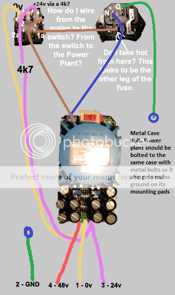
Is there any preference for the cable to be used from the PSU and the preamp. I use the Power Plant kit from JLMAudio so I would need 3 wire plus shield, right ? (0, 24, 48 + ground).


I have another question concerning the place chosen to put the PSU. Since the Powerplant fit in a 1U rack space, is that a good idea to rack it under (or above) the unit of the preamp. Or should it be as far away as possible. Thanks a lot.
Alex
 
alexidoia said:
Hello there,
I can't figure out where this has been discussed (on which on the 75 pages) but I know I read it so excuse me to ask again.
Is there any preference for the cable to be used from the PSU and the preamp. I use the Power Plant kit from JLMAudio so I would need 3 wire plus shield, right ? (0, 24, 48 + ground).


I have another question concerning the place chosen to put the PSU. Since the Powerplant fit in a 1U rack space, is that a good idea to rack it under (or above) the unit of the preamp. Or should it be as far away as possible. Thanks a lot.
Alex

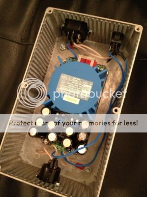
I had a 2U rack case in which I was going to mount the Power Plant. However, once I had both and was looking at both, I sent the rack case back and used a small hammond enclosure. The rack case was steel, and Joe recommends an aluminum case to act as a heatsink for the Power Plant. Also, it fits beautifully and is less expensive.

d9fd7304-7fd5-4219-a089-7407ff2b24fc_zpsdc2e107d.jpg
 
useme2305 said:
this is pretty basic stuff, indiehouse. if you cannot figure out how to wire a simple on/off switch by your self you probably shouldn't attempt a project like this in the first place.

my recommendation: grab a multimeter and the spec sheets of the switch and connector and find out how they work and how you can make them work in your project.

Sorry for the newb question. It's true I haven't wired in a mains switch before, but I'm learning, and I really appreciate the advice and knowledge imparted here. The spirit of initiative and learning is what I love about this forum.

I reached out to Joe from JLM, and he gave me some great pointers! I now know how to wire in mains (and referencespec sheets). Really appreciate it!

I am so close! I powered the Power Plant on, and nothing fried! That's a good sign. I adjusted the 48v rail as well as the 24v rail per via the trimpots. Beautiful.

Here's the first weird thing. When I turn the LED rocker switch off, the LED doesn't turn off right away. In fact, it slowly fades down, and I mean slowly. That doesn't seem normal, but the rails are reading fine.

Here's the second problem. I hook up the Power Plant to the pre's via the 4 pin cable, and I don't have signal. Phantom power works, though. I read the voltage across 0V and 24V, and it reads 1.5V. That's a problem.

I go back to the Power Plant, and 48V reads fine, but 24V reads 1.5V. Also, the LED does NOT light up now.

Here's the weird thing. When I unhook the 4 pin cable from the power supply, the LED works again, and I have 24V now. Well, sort of. I actually have something like 23.5, but the trim pot no longer adjusts the value.

I checked my wiring in the 4 pin cable, as well as in the pre. Everything is everything. It appears the 48V is working, but something is going on with 24V. I have attached a wiring diagram below.

Again, I really appreciate your guidance! I am so close here!

wiringcopy_zps6546fd39.jpg
 
So, I am trying one board at a time. With only 1 board powered, I get 3.5V. I've done each board individually, with the same results. I've disconnected the Go Between, input transformer, and trimmer switch with the same results, 3.5V.

Am I shorting out somewhere? Have I shorted out all 4 boards? Or is my problem with the power supply?
 

Latest posts

Back
Top