8 Channel, 3U NEVE 1073 completed

GroupDIY Audio Forum

Help Support GroupDIY Audio Forum:

This site may earn a commission from merchant affiliate links, including eBay, Amazon, and others.
Hi indiehouse,

just a suggestion put some heat sinks on those regs isolated of course,and see if you have the same probelm , it might be that the regs or going into thermal sunt down , just my 2 pence..

skal1
 
Thanks for the tip! I just tried that after reading your post...same result with a separate heatsink as when I use the aluminum case as a heatsink.

I hooked the PSU up to a board that has all the caps installed correctly. When measuring between 0V and 24V on the board, the reading fluctuates between 3.7 and 4.2 pretty regularly, from 3.7 up to 4.2 then back down to 3.7 and so on. The LED on the power switch faintly pulses now too.

I thought I might have had some luck after finding the backwards cap, but the same problem still persists.

I also tried adjusting the 5k trim pot on the EZ1290. To measure, I put my negative DMM lead on the 0V point and the positive on the screw that holds the 2N3055. The trim pot did nothing, and it measures around 3.2 or so.

I have no idea where to go now.
 
is the 2n3055 on the ez1290 board mounted correctly? check for continuity between its two small pins to the its housing and ground.
also, did you mix up the values of some resistors? maybe you confused kOhms with Ohms somewhere.

my guess is that you either installed a component incorrectly on the pcb on all four of them or you installed a wrong component on all four of them.

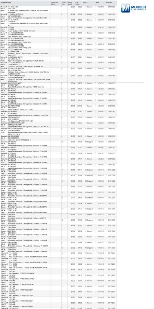
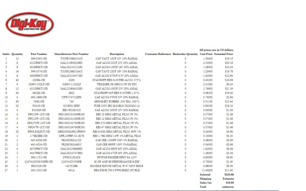
what BOM did you use? did you create your own cart at some retailer for components? maybe you can post a pdf or scan/pic of the receipt with a list of components from your purchase for this project.
 
useme2305 said:
is the 2n3055 on the ez1290 board mounted correctly? check for continuity between its two small pins to the its housing and ground.
also, did you mix up the values of some resistors? maybe you confused kOhms with Ohms somewhere.

my guess is that you either installed a component incorrectly on the pcb on all four of them or you installed a wrong component on all four of them.

what BOM did you use? did you create your own cart at some retailer for components? maybe you can post a pdf or scan/pic of the receipt from that purchase.

I believe the 2N3055 is mounted correctly, as it would only mount one way. I will check though.

I feel good about my resistors. I checked every one with a DMM before installing to avoid installing an incorrect resistor. However, at this point, I will check again.

I used the most current BOM from page 1 of this thread. I sourced parts from Digi-Key, Mouser, Small Bear and eBay. I have attached my invoices below.

eBay_zps0299cf9f.jpg

SmallBear_zpsca332e21.jpg

MouserOrder_zps29536dd4.jpg

DigikeyOrder_zpsc469ca5d.jpg
 
how about the 10k resistance, is that one to be put only if we don't use a jumper or what ?

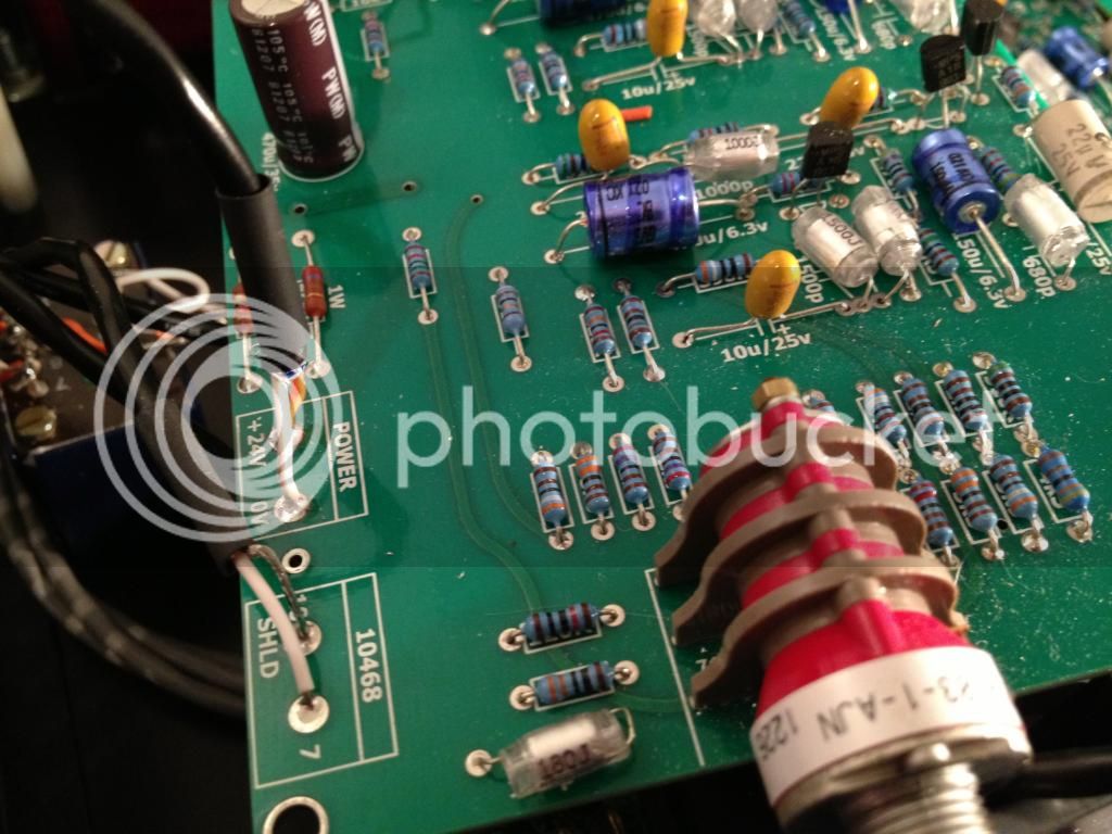
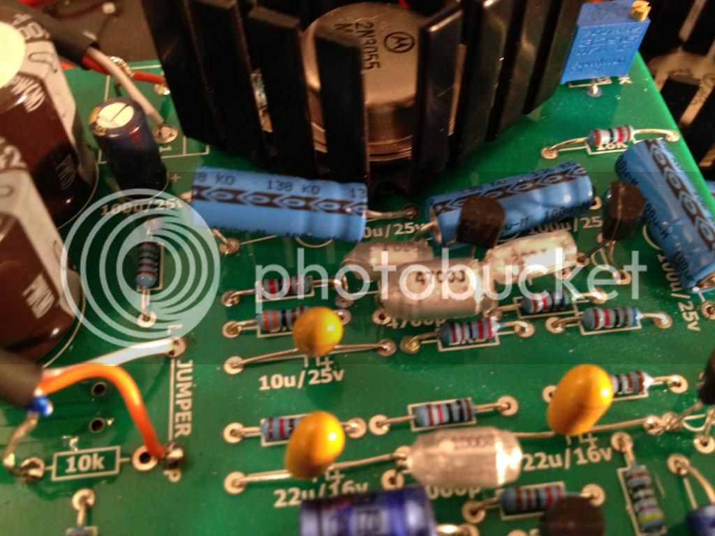
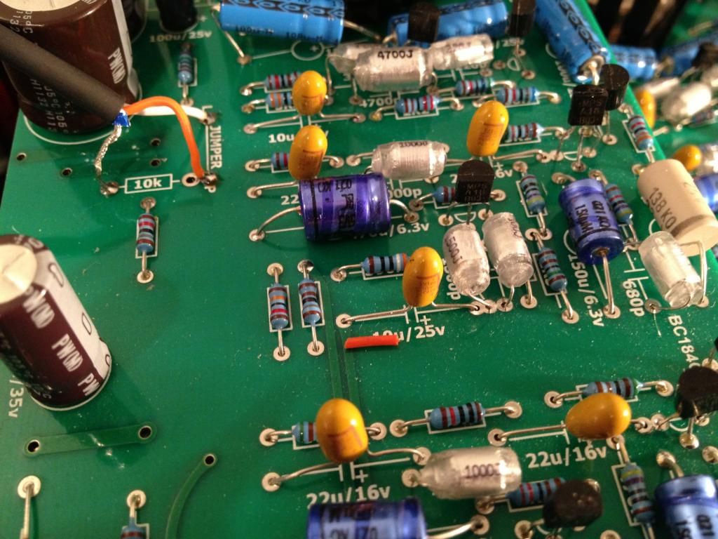
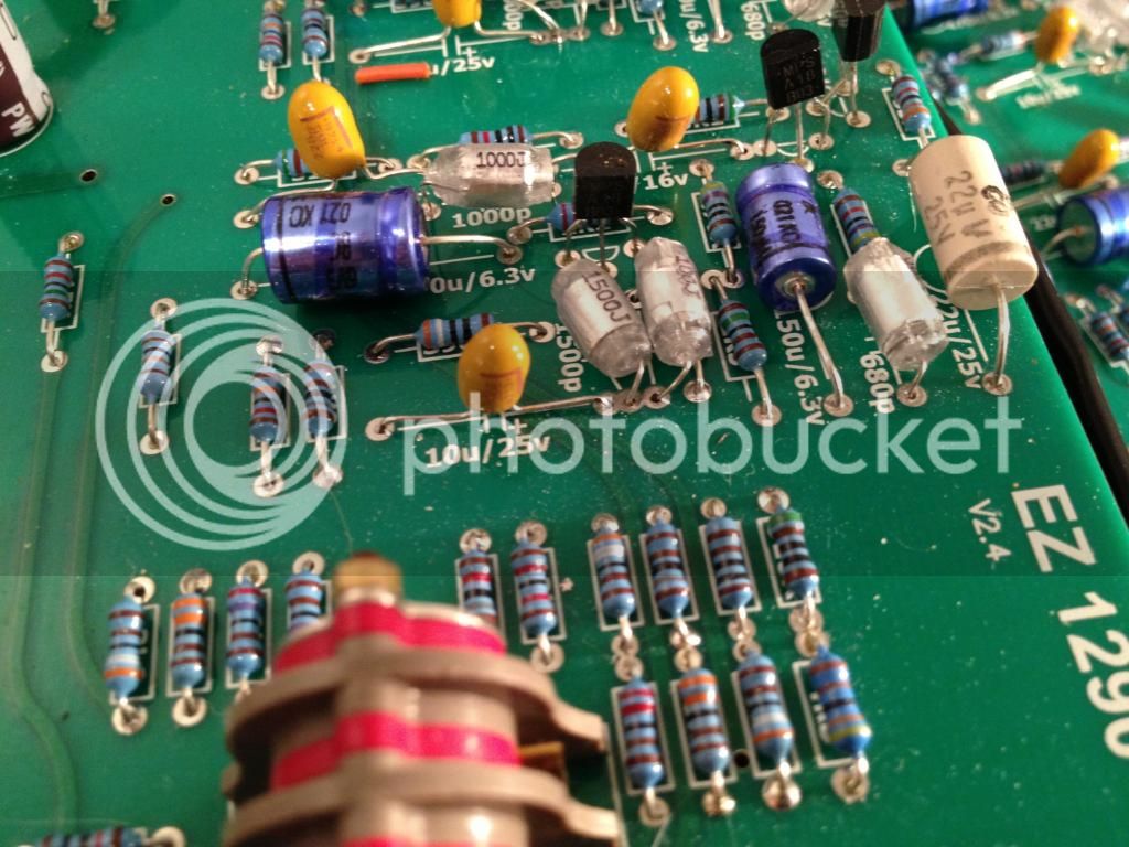
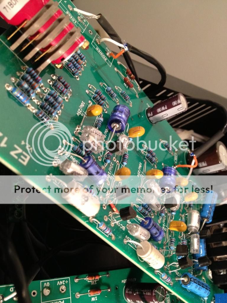
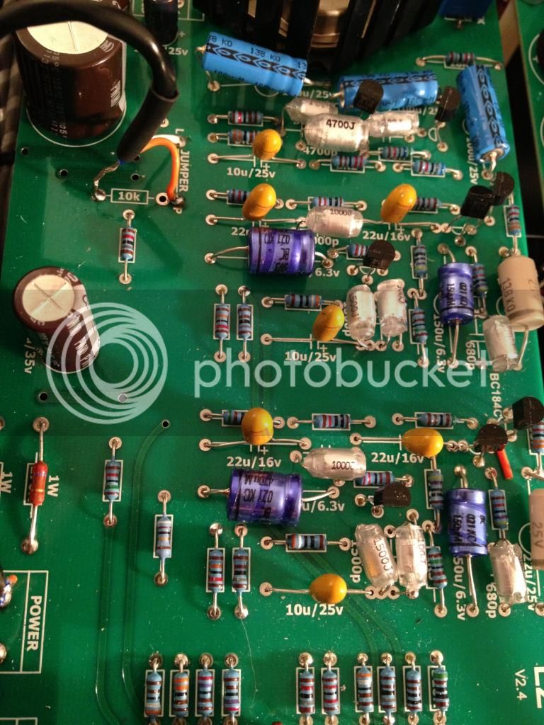
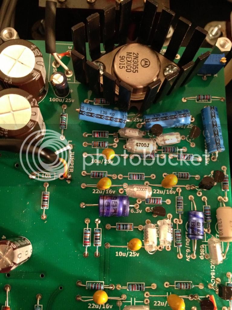
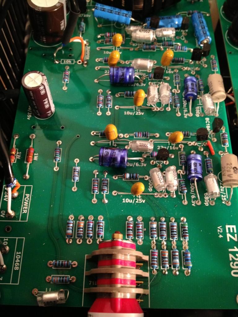
At this point, I'd like to ask you to get clean and steady shots of your PCB (again) on different angles so we can also checked the polarity of your ceramic caps. Make the shots big (2500px wide is cool) and zip them.
Alex
 
alexidoia said:
how about the 10k resistance, is that one to be put only if we don't use a jumper or what ?

At this point, I'd like to ask you to get clean and steady shots of your PCB (again) on different angles so we can also checked the polarity of your ceramic caps. Make the shots big (2500px wide is cool) and zip them.
Alex

I will do it. Thank you all so much for helping me figure this out!

sr1200 said:
wonder if he melted some polystyrenes?

Would this be visible damage?

So, if I'm thinking about this right, if the PS reads 24V without a load, and 3.7V with a load, that means the board is drawing way too much current, right? This would most likely occur due to a short somewhere, yes?

Could it be a damaged regulator on the PS? Joe from JLM said that if the regulator goes bad, it usually reads full rail at 35V.

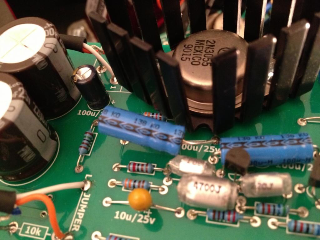
Could it be a bad/counterfit Motorolla 2N3055? I've read that these are popular to counterfit, for whatever reason.
 
sr1200 said:
wonder if he melted some polystyrenes?
He might have but should still output some sound. I had that on an preamp and the sound was distorsed, but the signal went through. I think something must have gone wrong at first power up and broke something, maybe bad polarity.

@indiehouse
Did you try out all board at once ? Did you try to send a signal of any sort and see what comes out ?
 
Damaged polys wouldnt necessarily be a visible thing.  If you melt the core of them from letting the iron sit on the lead too long you might not see it.  (and they are not very difficult to damage with a really hot iron).  Also the trim pot on the board is for bias.
 
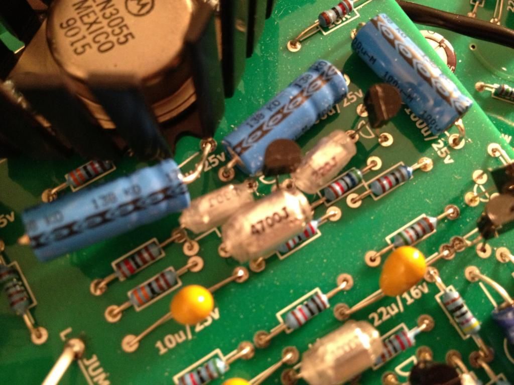
just a thought. Looking at your PCB and comparing to mine, some legs of your polys are really close to each other, especialy in the driver stage. I remember there was a difficult area to place the polys correctly, are you sure legs are not touching each other ? Same question regarding the caps near the heatsink. martin adviced not to place it horizontaly, I tried too to see if I could fit it and remember it to be way too close from other legs or to the heatsink itself (which I did not want to be touched) or to the resistor right below it. Check there too.

Finally and that is a question to martin if he's not bored yet by this thread :).
I have PCB version 2.1 and I noticed that from version 2.4 the two electrolytic caps have changed diameter, mine read 470uF 35v, did you change that ? and can I ask why ? I read 22uF 25v on the indihouse 2.4 version board.
 
alexidoia said:
sr1200 said:
wonder if he melted some polystyrenes?
He might have but should still output some sound. I had that on an preamp and the sound was distorsed, but the signal went through. I think something must have gone wrong at first power up and broke something, maybe bad polarity.

@indiehouse
Did you try out all board at once ? Did you try to send a signal of any sort and see what comes out ?

Yes, the first time I powered up, I had all four boards connected. I realize that's a mistake. I should have done one at a time. The only time I had tried to get signal was that first time I powered all four up. I didn't get any signal then, but I haven't tried since. I will try again tomorrow using only one board.

sr1200 said:
Damaged polys wouldnt necessarily be a visible thing.  If you melt the core of them from letting the iron sit on the lead too long you might not see it.  (and they are not very difficult to damage with a really hot iron).  Also the trim pot on the board is for bias.

I read about that the poly's were sensitive to heat. As a precaution, I used a soldering heat sink clip tool when I installed all of my poly's.

Relevant to the trim pot, it adjusts the bias of the 2N3055? Would that affect current draw any? If I had one DMM lead on 0V and the other on the screw for the 2N3055, shouldn't the trim pot adjust the collector voltage? Am I not getting enough power to the board for this to work yet?

alexidoia said:
just a thought. Looking at your PCB and comparing to mine, some legs of your polys are really close to each other, especialy in the driver stage. I remember there was a difficult area to place the polys correctly, are you sure legs are not touching each other ? Same question regarding the caps near the heatsink. martin adviced not to place it horizontaly, I tried too to see if I could fit it and remember it to be way too close from other legs or to the heatsink itself (which I did not want to be touched) or to the resistor right below it. Check there too.

I've had a look over several times, and didn't see any legs touching each other. I will look again, though.

I know I've said this before, but I really appreciate the help! I'm super stressed, and it's weighing heavy on my mind that I have a giant paperweight sitting on my bench.

alexidoia said:
how about the 10k resistance, is that one to be put only if we don't use a jumper or what ?

At this point, I'd like to ask you to get clean and steady shots of your PCB (again) on different angles so we can also checked the polarity of your ceramic caps. Make the shots big (2500px wide is cool) and zip them.
Alex

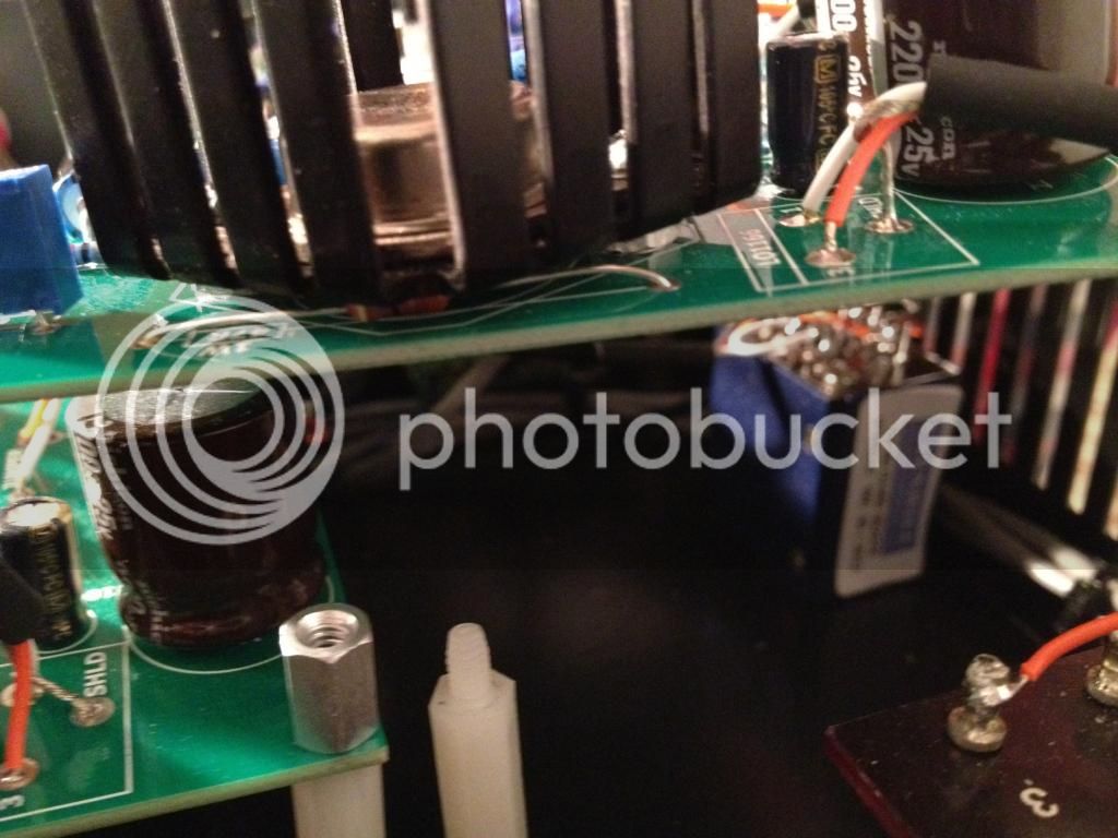
I tried the zip, but it didn't work. Hopefully having these pics in the message is ok.

IMG_2664_zps1302aca4.jpg


IMG_2663_zpscf6db996.jpg


IMG_2662_zps10a8b044.jpg


IMG_2661_zps5cb4f80f.jpg


IMG_2660_zpsb73565a1.jpg


IMG_2659_zpsd9a78a0c.jpg


IMG_2658_zps67dfb0c7.jpg


IMG_2657_zpsae42fb09.jpg


IMG_2656_zpse86ea060.jpg


IMG_2655_zpsc4a95a78.jpg


IMG_2654_zps46600121.jpg


IMG_2656_zpse86ea060.jpg
 
Can't see anything wrong except the fact your boards are dirty  :p.
Did you go through the list of things to check from the FAQ ?
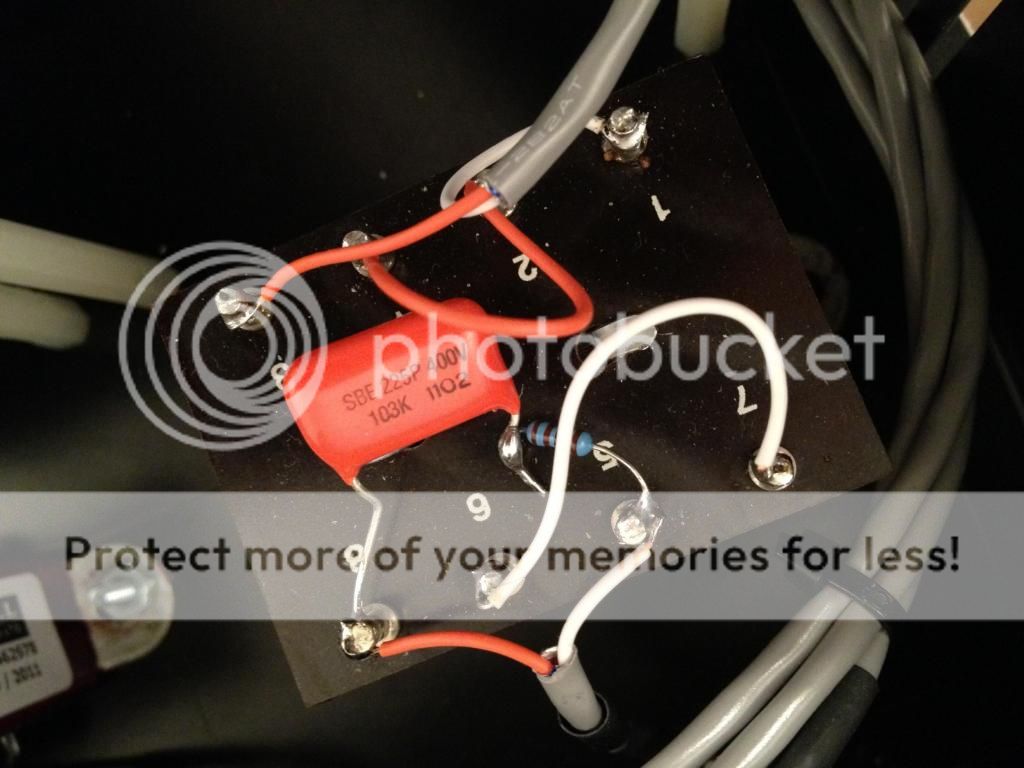
Did you add the resistor and cap on the Output trans ?

I don't know what else to tell you, is there not a list of current measurements to be checked to isolate the problem ?
 
alexidoia said:
Can't see anything wrong except the fact your boards are dirty  :p.
Did you go through the list of things to check from the FAQ ?
Did you add the resistor and cap on the Output trans ?

I don't know what else to tell you, is there not a list of current measurements to be checked to isolate the problem ?

I noticed that the dust really showed up in the pics. In person, the boards look clean. I will dust these off with some air duster.

Here is the output tranny. I used a 400V Orange Drop cap on the output (.01uF), the one listed on the BOM.

outputtranny_zpsbcea18a0.jpg
 
OK that lil amount of dust isnt going to cause this.  Some things i notice
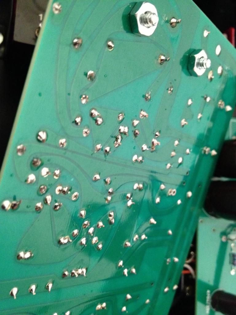
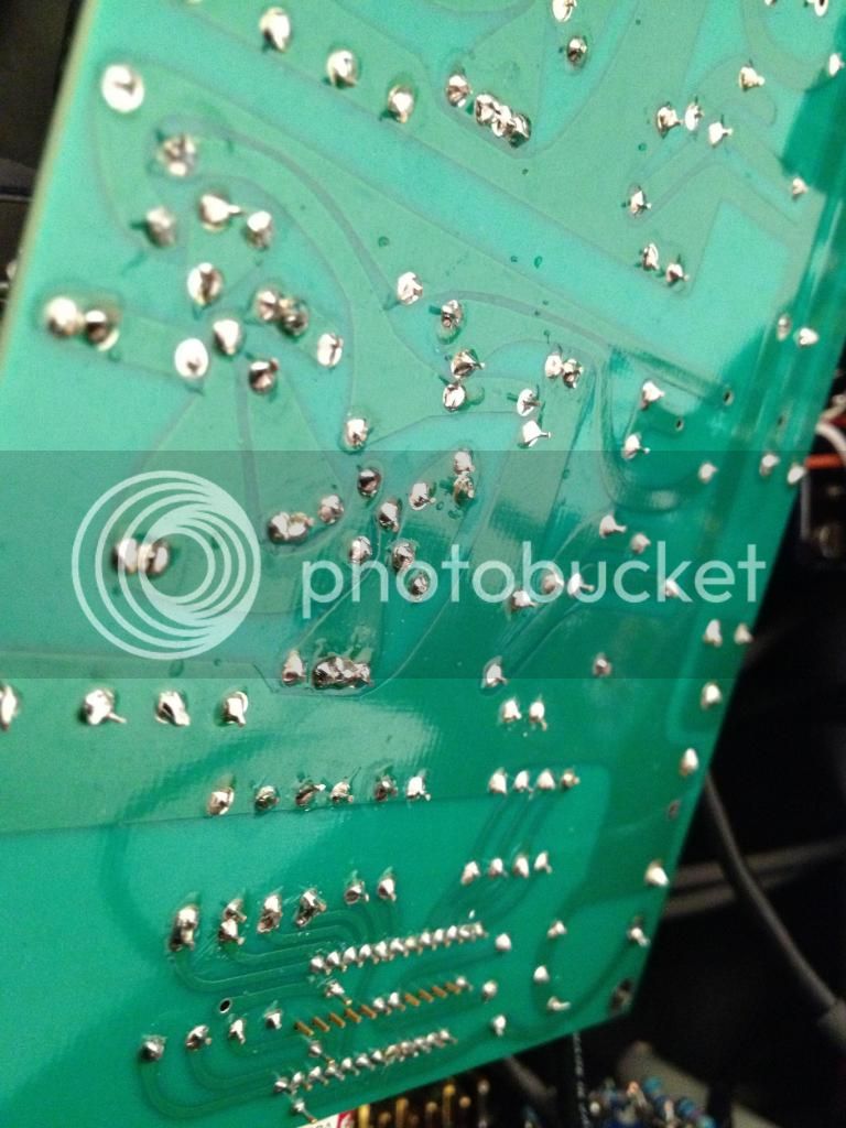
1) you used VERY little solder on a lot of your pads. When you see the component leg have wiggle room on the top of the board that kinda makes me feel like there could be issues underneath.
2) That resistor thats buried underneath the transistor is going to cook, you need to get that out from under the heat sink (which is why the board has the little rectangle where the component should be so that it clears the heat sink, most likely NOT the issue but it may become one down the road).

Lets trace the power input.  Make sure none of your components are open.  Check R56 R51 C4 C5 C7 C8 and R98

And just to reiterate, all your transformers are hooked up when you're testing, correct?

Take one of your boards and re touch the solder joints, add a bit more to fill the thrus, (dont glob it on, just make sure its a solid joint) you may have missed a pad somewhere or have a cold solder that you cant see with the naked eye (magnifying glass helps sometimes, but its just easier to re-touch the board).
 
sr1200 said:
OK that lil amount of dust isnt going to cause this.  Some things i notice
1) you used VERY little solder on a lot of your pads. When you see the component leg have wiggle room on the top of the board that kinda makes me feel like there could be issues underneath.
2) That resistor thats buried underneath the transistor is going to cook, you need to get that out from under the heat sink (which is why the board has the little rectangle where the component should be so that it clears the heat sink, most likely NOT the issue but it may become one down the road).

Lets trace the power input.  Make sure none of your components are open.  Check R56 R51 C4 C5 C7 C8 and R98

And just to reiterate, all your transformers are hooked up when you're testing, correct?

Take one of your boards and re touch the solder joints, add a bit more to fill the thrus, (dont glob it on, just make sure its a solid joint) you may have missed a pad somewhere or have a cold solder that you cant see with the naked eye (magnifying glass helps sometimes, but its just easier to re-touch the board).

Yep, both transformers are connected.

What do you mean when you say to make sure none of my components are open? I'm I tracing the 24V through these components? (meaning on DMM lead on 0V, and the other on each of these components?

Also, I soldered from the back of the board. Should I solder from the front as well?

IMG_2667_zpsf141b3f4.jpg


IMG_2666_zps9a47b8fe.jpg
 
what im talkin about is say you have a XXXresistor,  has no voltage going through it at all. You can even have a resistor that may read 0ohms... Bad resistor, bad cap.  Chances that it happened on 4 separate boards... slim. But if you havent checked each board individually, hard to tell.  At this point im going to call shenanigans  on the replacements for the BC's ya put in. Im going to pull one of my boards out tonight and AB it with yours. 
 
sr1200 said:
what im talkin about is say you have a XXXresistor,  has no voltage going through it at all. You can even have a resistor that may read 0ohms... Bad resistor, bad cap.  Chances that it happened on 4 separate boards... slim. But if you havent checked each board individually, hard to tell.  At this point im going to call shenanigans  on the replacements for the BC's ya put in. Im going to pull one of my boards out tonight and AB it with yours.
Very kind ! (it is not for me, but I found that very cool).
As for the amount of solder, putting aside the cold ones of course, there is no need to have solder that fills the 2mm deep (thickness of the board) of the whole (the thrus ? I did not know that term).  Personally your pads look good to me as long as they have that nice uniform cone at the end of the leg at the back of the PCB. Having said that, some of them have not that cone on the last picture you sent and they do miss a little solder to me. But that juste me, my knowledge is quite limited but I know how to solder ;)

I recommend cleaning the boards with some kitchen roll and alcohol.
 
alexidoia said:
Very kind ! (it is not for me, but I found that very cool).
As for the amount of solder, putting aside the cold ones of course, there is no need to have solder that fills the 2mm deep (thickness of the board) of the whole (the thrus ? I did not know that term).  Personally your pads look good to me as long as they have that nice uniform cone at the end of the leg at the back of the PCB. Having said that, some of them have not that cone on the last picture you sent and they do miss a little solder to me. But that juste me, my knowledge is quite limited but I know how to solder ;)

I recommend cleaning the boards with some kitchen roll and alcohol.

I will clean my board and re-touch my solder pads. Thanks!

sr1200 said:
what im talkin about is say you have a XXXresistor,  has no voltage going through it at all. You can even have a resistor that may read 0ohms... Bad resistor, bad cap.  Chances that it happened on 4 separate boards... slim. But if you havent checked each board individually, hard to tell.  At this point im going to call shenanigans  on the replacements for the BC's ya put in. Im going to pull one of my boards out tonight and AB it with yours.

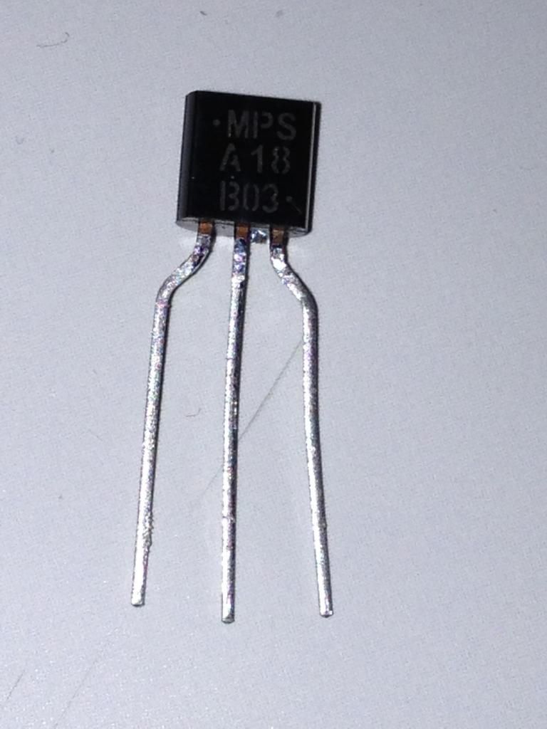
You think I have some bunk transistors? Or maybe the orientation isn't right? I have enough BC184C's to do one board, if you think these may be the culprit. I was going to sell them, since I only had enough to do one, but picked up a lot of 100 MPSA18's for fifteen dollars on eBay.

tranny_zps173688f0.jpg
 
Back
Top