zachs
Well-known member
Just want to say this thread/project is still 100/100. So impressive.


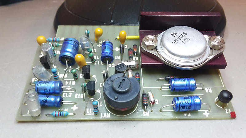
>> Why is -- R6 -- shown as being a capacitor? Is this an "OOPS"??? Or, some kind of "secret MOJO" modification???.....

This is a big oops on the silkscreen! This is C7 and R6 is the resistor just behind>> Why is -- R6 -- shown as being a capacitor? Is this an "OOPS"??? Or, some kind of "secret MOJO" modification???.....
View attachment 140783
/
") The trace appears to be the same as an usual B283
The trace appears to be the same as an usual B283 
I just checked Mouser, and they have several 1W 270R in metal film, from Yageo, TE, and Vishay. I wouldn’t use 1/4W where a 1W is specified.I just realized I've ordered a 1/4 270R resistor when the BOM states it should be 1W , is there going to be an issue if I keep the 1/4w? The only ones I could find in 1W are carbon film but I'm not sure if it might increase noise/distortion ( never used them before and I keep reading about how noisy they are )
Thank you
Appreciate the feedback! Do you think if I use carbon film , there is going to be a difference in noise? It's gonna be a bit expensive to order just 1 resistor from mouserI just checked Mouser, and they have several 1W 270R in metal film, from Yageo, TE, and Vishay. I wouldn’t use 1/4W where a 1W is specified.
I just realized I've ordered a 1/4 270R resistor when the BOM states it should be 1W , is there going to be an issue if I keep the 1/4w?
Appreciate the feedback! Do you think if I use carbon film
there is going to be a difference in noise?
[I'll get the carbon film 1w!] -- "Metal-Film" will be even better and there is basically no price difference than that of "Carbon-Film". Metal-Film resistors will have even lower noise.Thank you @Whoops ! I followed the BOM to the t , even went with military resistors for the sake of double checking the values visually !
The 1w somehow slipped through. I'll get the carbon film 1w!
Thanks !
All my transistor values are extremely close to the build guide reference except TR1 emitter. I get 350mv instead of 0.4v


Just to make sure I understand, with no signal going in, phantom power off, you turn up the gain and measure 50VDC on the output xlr pins + and gnd?Hello everybody! I'm a DIY newbie, I've been reading this forum for a long time and I really appreciate the patience and knowledge you give to newbies like me. EZ1290 isn't my first project but probably the most challenging I've tried.
I finished my 2 channel unit, with trim, line input (with fixed pad), impedance selector and a board I specifically designed to support Alps spun pushbutton for +48, phase and pad. I couldn't find a PCB-mount grayhill switch in stock so I did it with panel mount ones that made the cabling a little bit more messy (photo of the inside attached).
The unit works fine and sound great until I set the gain to the last two positions (70 and 75 dB). Here the noise become unacceptable, I measured the output (+ to gnd) with the scope and found out that I got 23V on 70dB setting and almost 50V on 75dB setting. This problem is the same on both channels. I read a lot of posts on this thread and already doubled checked the resistor's values, caps orientation and the transistor voltages are close enough to the tab on the assembly guide.
Can anyone please help me to figure out what can be the cause of this issue?
Thank you!!
(please be kind with my english, this is my first post)