Another headphone amp

GroupDIY Audio Forum

Help Support GroupDIY Audio Forum:

This site may earn a commission from merchant affiliate links, including eBay, Amazon, and others.

Val_r

Well-known member
Joined
Jun 5, 2004
Messages
306
Location
Naples, Italy.
Hi,

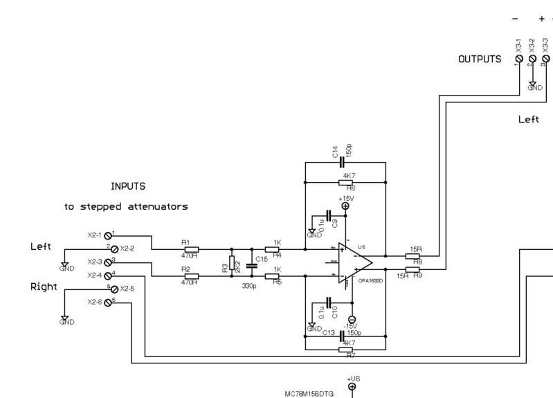
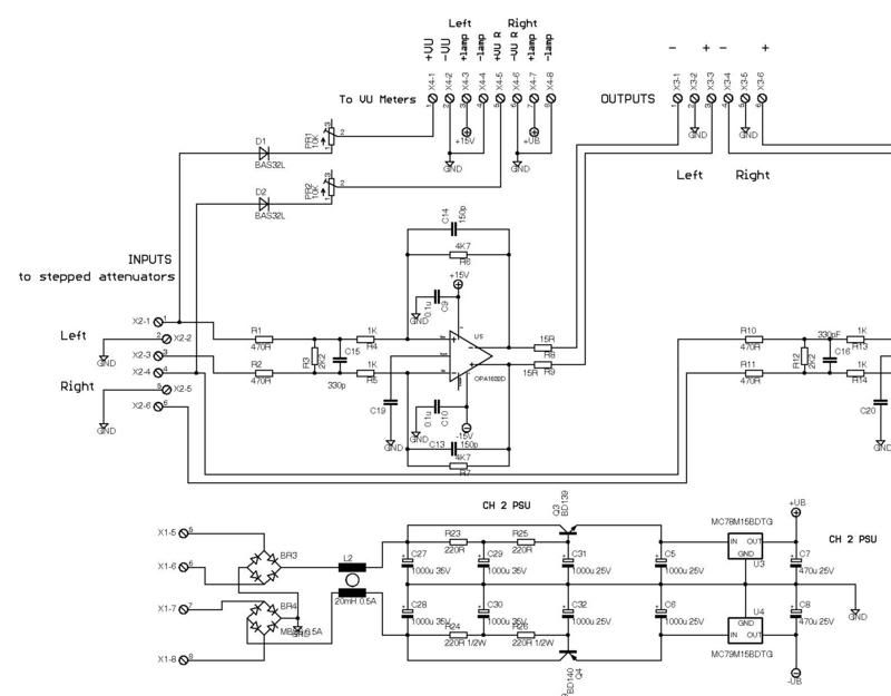
I started designing this one to fulfill the need of a flat and accurate amp for balanced headphones, where gnd is used as a RFI-EMI screen, + and - of driver directly connected respectively to + and - of coil.
The OPA1632D differential op amp was used, with an overall gain of about 2.

Please post suggestions/comments.

Thank you,

Val.

hpbal.jpg
 
Consider the TI THS4502, a 15V-part (which should be enough for headphones). Its output current is 100mA into a 20R load. It's even faster than the OPA1632 (350MHz GBW); the only downside is a higher 1/f noise knee -- not something you'll likely notice in a headphone amp.

Caveats for both chips: First, with fast devices like these you must roll off gain or you'll be building an RFI/oscillation nightmare. 150pF across both R6 and R7 is a good starting point; perhaps add a 330pF cap across R3 as well. Second, power dissipation for these packages is rather limited (~1W), putting a ceiling on your max output levels.

JDB.
[the TPA6120A2 in differential (BTL) mode might even be a better match here]
 
What do you think of this chip?

http://focus.ti.com/lit/ds/symlink/tl592b.pdf
 
[quote author="Wavebourn"]http://focus.ti.com/lit/ds/symlink/tl592b.pdf[/quote]
Oh dear, our old friend the TL592 alias NE592 alias uA733. Saw this part first over twenty years ago, and I never really liked it; the DIP8 is very prone to oscillate because the input and output pins are too close; the DIP14 is very prone to oscillate because the chip lead frame has a huge inductance compared to the part's bandwidth. The best that could be said of it is that it has plenty of second sources, albeit with a few subtle variations.

For this application it doesn't have enough output drive.

JD 'the horror' B.
 
[quote author="jdbakker"]

Caveats for both chips: First, with fast devices like these you must roll off gain or you'll be building an RFI/oscillation nightmare. 150pF across both R6 and R7 is a good starting point; perhaps add a 330pF cap across R3 as well. Second, power dissipation for these packages is rather limited (~1W), putting a ceiling on your max output levels.

JDB.
[/quote]
oh , that's right man!
hpbal-1.jpg


I think I will use THS4131ID, since it can give 85mA on 7 ohms!


[quote author="mediatechnology"]I didn't see whether pin 2, Vocm, output common mode, should be open or grounded for 0V Vocm. I'm pretty sure it should be ground tied or at least bypassed.[/quote]

I think you can leave it, am I wrong?

Do you think that a 10K log. at the inputs will do?
 
[quote author="Val_r"][quote author="mediatechnology"]I didn't see whether pin 2, Vocm, output common mode, should be open or grounded for 0V Vocm. I'm pretty sure it should be ground tied or at least bypassed.[/quote]
I think you can leave it, am I wrong?[/quote]
You could leave it and live with the higher CM output noise, but I agree with Wayne that a capacitor or a direct connection to ground is better. Put in pads for the cap and see which (cap, open, short to ground) 'sounds' better.

[quote author="Val_r"]Do you think that a 10K log. at the inputs will do?[/quote]
How are you planning to wire it ? Your differential input impedance is ~2k, or ~1k per leg. A 10k input pot would see way too much load if you just connect this amp to the pot wiper. Other configurations are possible (remember that a fully-diff amp can be seen as a fancy virtual-ground bus summer).

JDB.
 
[quote author="jdbakker"]
You could leave it and live with the higher CM output noise, but I agree with Wayne that a capacitor or a direct connection to ground is better. Put in pads for the cap and see which (cap, open, short to ground) 'sounds' better.[/quote]

I will try that as suggested

[quote author="jdbakker"]How are you planning to wire it ? Your differential input impedance is ~2k, or ~1k per leg. A 10k input pot would see way too much load if you just connect this amp to the pot wiper. Other configurations are possible (remember that a fully-diff amp can be seen as a fancy virtual-ground bus summer).

JDB.[/quote]

This is what I had in my mind (only one channel shown)

balpot.jpg
 
I have updated the schematic (refer to the first drawing)
added a filter on PSU with a common mode inductor for positive and negative rail.

I hope that filtering the power supply this way should improve the amp overall performance, what do you think?

I also added a metering feature, a mere average indication, since it is connected only on the positive going phase of each input.

Your suggestions/comments are more than welcome.

Respect,

Val
 
Back
Top