ForthMonkey
Well-known member
Now i'm making pcb for voltage follower.But...Where is the GND? Circuit working in spice without GND pin.There are only +/-V-In-Out pins.
But this design has GND.
http://www.diyrecordingequipment.com/projects/classicapi-discrete-voltage-follower/
I don't understand.Can you help?
Thanks.
But this design has GND.
http://www.diyrecordingequipment.com/projects/classicapi-discrete-voltage-follower/
I don't understand.Can you help?
Thanks.
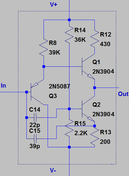
 nly four pin.In,Out,-V,+V.But in real life circuit has 5 pin with GND.I can't understand that where is the GND?