API 312 Thread!

GroupDIY Audio Forum

Help Support GroupDIY Audio Forum:

This site may earn a commission from merchant affiliate links, including eBay, Amazon, and others.
The 312 outputs have 4 equal windings. On the datasheets sometimes they are drawn with one as primary and three as secondaries, sometimes as 2 and 2, sometimes all four on one side.  You can pick any one as your primary, then use the rest in series as your secondary (or 2 as sec and one to drive a VU), just make note of the beginnings and ends of the windings. Check the Cinemag datasheet for a visual. 
 
Back again with mostly the same problems as above.

Here's where i'm at now: I have mounted one of my 312 channels in the chassis in an effort to ensure proper grounding because bicyclerecording's 312 card is grounded to chassis via the PC mount input XLR.

I turn it on and i'm still getting some noise/oscillation at the lowest and highest frequencies, but the amp's working at medium gain settings. But i noticed, when i touch the can of the input transformer (cinemag) that the noise is significantly reduced. So i makeshift another ground by touching the can of the transformer to the chassis via a file and the noise seems to be pretty much gone.

Does anyone have any suggestions on how to permanently remedy this/what is going wrong? Could it be that i'm just not getting a good enough chassis ground on the input xlr? Should i try scraping off the paint around the xlr or something?

Thanks.
 
If you had your chassis engraved to the Neutrik specs it should be getting a good ground, but you could also try scraping off the paint on the inside where the jack is contacting the chassis. The chassis is connected to the ground network the round 3rd pin on your AC receptacles) of your house, correct?

Would you be able to take a photo of the PC card and how it's mounted/grounded and post it or email it to me if you can't post it?

The Cinemag 75101 on this board is actually slightly different than is shown on the schematic I have supplied. The shield for this transformer is connected to audio ground. If you ground the shield to chasses ground you'll be routing the rest of the audio ground here too which may be worth considering depending on how the audio ground is otherwise connected to chassis ground (for example, it is sometimes connected with a 10r resistor and capacitor (this is true for the JLM power supplies, you have one of these correct?)).
 
Heyho,

the first channel is already up and running - the amount of gain this thing delivers is just insane?!? I can speak(!) in a 58 with the gain-pot 'off ' (no pad) and I get sufficient level in my daw. How should I ever record a snare drum without clipping my ad converters :D

cheers
christoph
 
Ok. Are you using his stock BOM? If the input transformer is wired 1:10 you'll end up with a pretty high low gain setting (32 dB according to his schematic), which is why installing a pad in the circuit is a really good idea. With the transformer at 1:10 even a 20 dB pad often isn't enough.
 
My input tranny is a CMMI-8PCA, which should be 1:8 - but yeah, still a quite high ratio :D

I'm gonna give it a try with a percussive signal, otherwise I'll build a passive XLR pad for the input...

cheers
christoph
 
The chassis is connected to the ground network the round 3rd pin on your AC receptacles) of your house, correct?

Yeah. I've tried both with and without that connected (via alligator clips) to chassis.

Would you be able to take a photo of the PC card and how it's mounted/grounded and post it or email it to me if you can't post it?

Yup. Here's links. I apologize in advance for the god-awful quality of the pics... pretty terrible lighting in my apartment bedroom...

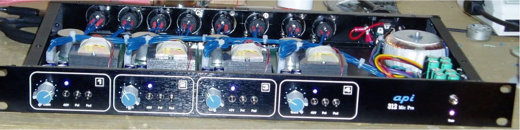
The first one is supposed to be showing my ground network. Red alligator lead/cable going from ground pin of IEC jack to bolt on the JLM supply (thats what it said to do on their website i think). Yellow alligator clip going from that same bolt on the PSU to chassis:

http://img16.imageshack.us/img16/5501/img0925c.jpg

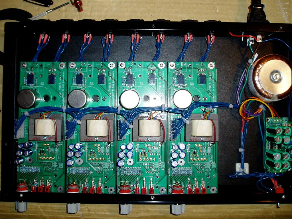
The rest are just a bunch of random pics of the board... nothing to specific... but if you can pick out something i'm doing wrong, great!

http://img19.imageshack.us/img19/2815/img0926b.jpg
http://img24.imageshack.us/img24/1725/img0928u.jpg
http://img22.imageshack.us/img22/8263/img0929t.jpg
http://img27.imageshack.us/img27/277/img0930h.jpg
http://img7.imageshack.us/img7/3762/img0931k.jpg
http://img27.imageshack.us/img27/3546/img0932i.jpg

The Cinemag 75101 on this board is actually slightly different than is shown on the schematic I have supplied. The shield for this transformer is connected to audio ground. If you ground the shield to chasses ground you'll be routing the rest of the audio ground here too which may be worth considering depending on how the audio ground is otherwise connected to chassis ground (for example, it is sometimes connected with a 10r resistor and capacitor (this is true for the JLM power supplies, you have one of these correct?)).

Ok i'm open to trying anything... i'm a bit of a noob though so i don't really know what to do haha. And yes i'm using the JLM 5 rail supply.

Thanks a ton for your help, Bob. Also, do you happen to have a layout or a good close up of your boards... i have both my boards stuffed but i just want to make sure that i have all the components in right...

 
Guitarguy,

Judging from the picture of the bottom of the board, I'd say forget grounding and take a VERY CLOSE LOOK at the bottom of your board. Check all the solder joints. Every one. (Don't worry I did this on my first attempt too, the SSL9k, a lot more solder joints to re-do) You should not have any round, ball-looking solder joints (like on your switches, and where the brown trafo wire goes to, for example). And I can't really tell but the soldering on some of the gain switch resistors looks like it has pits in it (maybe it's just a reflection) Anyway, you shouldn't have that either.
All your joints should have shiny mirror-like CONCAVE surfaces. Like tiny little Hershey Kisses. (How's that for a visual?) Make sure that's correct first, then connect everything back up (except the opamp), turn on, check DC, turn off, plug your opamp and see what you got.
good luck, hope you get it working soon.
 
Oh, one thing that might be worth checking, you ought to have some sort of space or spacer (piece of paper or just mount it away from the board a little) between the input xformer and the board. There is the potential for shorts to be made between different signal paths the the bare transformer is seated against the PCB. I don't think this would cause nor solve a hum issue but maybe it would. Whatever the case, this would be good to do if it's not done.

I'm not seeing anything else too obvious. I'll try to take some good photos of my built boards tomorrow.
 
Well almost finished my first API.

Just waiting on opamps from Fabio.  ;D
Wondering what the maximum voltage the OpAmps can take? I've heard of a few people blowing theres and wondering what are the main causes of this???
P1010086.jpg

P1010087.jpg
 
That looks great RRS. Have you been able to test them out yet with any op amps at all?

2520s are generally run at 16 or 17V AFAIK.

It's great to see some of the board getting built up!

What files did you work off of for the panel layouts? The Front Panel Designer files or the images with all the measurements?
 
bobschwenkler said:
That looks great RRS. Have you been able to test them out yet with any op amps at all?

2520s are generally run at 16 or 17V AFAIK.

It's great to see some of the board getting built up!

What files did you work off of for the panel layouts? The Front Panel Designer files or the images with all the measurements?

Yes, I'm interested in this too.

Nice looking unit here. That looks like a JLM Audio power supply.


Used the Front Panel Designer and got the front panel mesurement's from Bob's site.

Havn't tries any Opamps yet but Fabio's should be here soon.

My only concern is regarding matching transistor's. Which ones and how best to do it??
 
Is Fabio selling opamp boards? Thought it was just completed opamps. Anyway, if you are getting unbuilt ones, match the two transistors on the input (NPN, BC550 usually). I used the hFE adapter on my multimeter to come as close as possible. Doesn't have to be exact, but should be very close. Start out with a lot of them, and start making pairs. Then use your highest hFE pairs for the input pair of the opamps. So they should be matched and they should be high hFE. The higher the hFE of this pair, the less noise in the opamp, or so I've understood it.
 
I'd be interested to compare 2520s built with matched transistors. I didn't match mine and it seems great though there probably is a little improvement to be had. I remember reading on this board at some point about how the early 2520s and other op amps were probably not built with matched input transistors... May be true or may not be but whatever the case, mine are working and sounding great.
 
Back
Top