API Mic pre (with Yamaha parts) ***COMPLETED***

GroupDIY Audio Forum

Help Support GroupDIY Audio Forum:

This site may earn a commission from merchant affiliate links, including eBay, Amazon, and others.
It's all how you look at it.

I was just just trying to keep the question alive... that's all.
Again, I'm sorry.

If you look back on page 3 of this topic I asked a similar question that never got answered & got left behind...

If I knew as much as you guys did I could give a lot more back but I don't... so I'm stuck asking a lot of questions.

I want to be a welcome part of this forum & will take your advise.

Do you guys remember when it all started clicking & you could see & feel how the circuits worked for the first time... not to mention when you did it yourself & it all worked... well, I'm there :green:

This thread alone has taught me more than I can ask for.

Kevin
 
[quote author="jspartz"]Very cool information here. Keep it going. I have a couple extra Yamaha block opamps and a pair of 2503 output transformers (group buy from the forum a while back). I think that this would be a great project for them. I am curious how well the JLM boards work out for you. That would make life very nice.

Jason[/quote]

From what Matt told me they should work great in the Dual 99v.
I think I'm going to hold off on the 99v boards & just get some power supply boards from them... Have to finish this 8 channel API/Yamaha parts pre before I move on. I think doing the 99v with these parts I'm going to end up with too many pre's with the same parts & SOUND too similar. Also, I'm just about done a 2 ch PM2000 rack which uses the same parts as this API/YAM 8ch I doing. I'm going to wait & build the 99v with Joe's op-amps & Lundahl trannys like Dave did.

I will be posting all the info & pics I can to help others who might want to try this too. The parts are out there & they're cheap :wink:

Kevin
 
Matt,
You said "from the PM2000's +4 gain setting;
220ohms in series with each leg and 330ohms across them. "

I may be looking at the schematic wrong but it looks like the resistors are in series = 220+560+750+560.

I'm not sure?
 
UPDATE:

rafafredd, Your values are very good.
R3 = 22k feedback
R2 = 100ohm gain limit
POT = 25k (but I'm not letting it go past halfway down - I will change this)
I think a 10k pot would be great.

This thing got some gain now :shock:
I don't hear any strange noises when maxed out. In fact the noise floor is VERY Low & now it REALLY kills the Presonus BUT I noticed a drop in the low end even when backed off...

Dave, Is this what you were talking about? If so I think 20k will put it right down the middle.

kevin
 
Joe is actually away on a working holiday at the moment so hes going to be slow with emails until next week, and chances are not many orders will ship until then.

Joe gets over 100 emails each day, most of which are questions that require thoughtful answers, so you can see why sometimes it takes a few days for him to reply.

Here are a few things to remember when youre emailing with an order or question, and this is for everyone not just kevin!

*Try to distill your question down to its simplest form, as the longer it takes to read and understand what youre getting at, the longer itll take to reply.

*Remember when its day time there its night time here so sending multiple emails while were asleep wont get them answered faster!

*If you ask for a shipping quote, we need your address!!!

*If you email with a troubleshooting question, be methodical and clear about what seems to be wrong, and work through the answers Joe gives even if they seem strange, before you get back to him with the results. If you do this your gear will be working sooner rather than later.

Im only mentioning this because we are a very small company and because of this we can sell extremely high quality kits and equipment to you guys at relatively low prices.

Were in the kit business because Joe really enjoys helping people learn about electronics and also restore old gear that would otherwise go to waste.

We dont make big margins on the kits, especially considering the amount of emails they generate. But Joe still gets really excited about new kit ideas - hes really more interested in surprising you guys with cool new ideas than figuring out how much money were going to make.

So what Im saying is please bear all of this in mind if sometimes we take a while to get back to you. Its one of the ways we keep the cost down and the quality right up.

:thumb:


Ive got more to post soon but ive gotta go to work and build some 99V opamps now!


M
 
Matt,
Thanks for the PM :green:

For those who are still with me:
I got the RMAA running last nite & did some ruff testing.

Matt - To match the Yamaha +4 input PAD I ended up with 2k on each leg & 330 across. Is there any way set RMAA to JUST ONE CHANNEL:?:

I'm not sure what to think of the results but here they are
-----------------------------------------------------------
Frequency response (from 40 Hz to 15 kHz), dB:
+0.04, -0.18

Noise level, dB (A):
-108.1

Dynamic range, dB (A):
104.2

THD, %:
0.0014

IMD + Noise, %:
0.0024
------------------------------------------------
Setup -
Keep in mind the pre-amp is still open on the table (pics earlier in this thread)
32bit (4-byte-PCM) 48k (not sure if these are optimal settings yet)
+4 i/o on soundcard - LYNX-ONE

I don't think there was much gain, the setting was much lower than I was using than with the sm58 hooked up... so I tried backing off the soundcards output to let me push the gain higher & this is what happened.

BTW, What is IMD :?:

Frequency response (from 40 Hz to 15 kHz),
dB: +0.04, -0.18
Noise level, dB (A): -108.5
Dynamic range, dB (A): 92.0
THD, %: 0.0017
IMD + Noise, %: 0.074
------------------------------------
IMD & THD got worse & still didn't have the gain as high as I want for testing... probably because it's still open?

I'm going to re-test tonite & post a full/ better report with pics.

MATT,
How do you deal with using only one channel & most important, testing high gain settings with this kind of setup (like +50 to 60db)

I still have to determine if my sound card is causing some of the artifacts/IMD.

Where can I find SINGLE reverse LOG taper 10k to 20k pots?
Anybody?


Thanks,
Kevin
 
IMD & THD got worse & still didn't have the gain as high as I want for testing... probably because it's still open?

Oh, man, it specs great. I have DIY tube preamps that reads 1% THD and sounds GREAT! :razz:

Some Vari mu comps in deep gain reduction can go even higher THD and sounds great. :?: Don´t ask me.

Other preamps with [lie]0.0000001% THD[/lie] sounds like shit.

Do not concentrate on specs too much. Make sure it´s stable, with no oscilation, and good frequency response. 0.07% THD is low, for transformer coupled discreet opamp design.

I´m not saying I don´t test my gear thought. I do test it and some of them specs very good, some not. Most of the time I pick the ones that do not spec that great when tracking. Why is it?

If it´s distorting badly, you should be able to hear it!

Does it sounds good to you?

Where can I find SINGLE reverse LOG taper 10k to 20k pots?

I think JLM can help you, but you might also consider using switches.

BTW, What is IMD

intermodulation distortion.
 
Can anyone recommend a Toroidal for +/-24 volt rails & 48v phantom for an 8ch & 2ch version of my API/YAM Pre?

I'm really having trouble finding what I need... Maybe one from AMVECO?

I just ordered a few JLM AC/DC's.


Matt,
Since you're familiar with the PM2000's could you recommend a Toroidal for racking a pair + Phantom?

I just don't want to order the wrong stuff... I did try searching but only got more confussed :? Where exactly should I put my meter (between) to test for current draw - Before tranny, after tranny or after power supply?

Kevin
 
hi kevin,
you could check out this page and then you can figure out the VA rating for your torroidal power transformer:
http://www.avellindberg.com/transformers/tech_notes/tech_notes4.htm
find out how many mA the single channel is pulling and add them up.
plug into formula on the website and you should have your answer.
also remember to add any amps being drawn by the lighting, etc.
hope this helps.
regards,
grant
 
I'm not sure exactly where to test... I've done it before on guitar pedals but this is different.

Phantom is easy but the 2 DC power rails confusses me... do you measure 1 leg & double it or is this even the right spot :oops:


While I'm on a roll asking way too many questions:

Are there any good layouts, API style with Phase, Phantom & Pad switches available around here :?: I'm slowly getting thru the API 312 THREAD but haven't found one...

All Fabio's links are no good.

I'd like to modify it, if there is one, to fit my project. I know the JLM would work but it's got more than I need + I'll need about 12 of them.

Kevin
 
Ok cool...
No I dont think you can set it to just one channel, but it doesnt matter. You just ignore the other specs, or even better, loop that channel of your card around so you can see what the specs of the card are.

However your soundcard specs wont be effecting the testing much, at least for what were looking for, which is:

*The shape of the freq curve and the 1db and 3db down points, which generally shows you what the transformers and the loads youve put on them are doing.

and

*The THD graph, which will show you how much 2nd and 3rd harmonic distortion there is, and also if there is anything strange going on in between the normal harmonics.

Noise and IMD are also relevant but as long as the noise is way down and you cant see a huge hump at 60hz (meaning theres hum getting in) and the IMD isnt too bad (it will get much worse as you drive the input transformer). By the looks of it, this is fine anyway.

If you could save the freq graph (zoomed in so it shows no more than +/-6db) and post it for us to see that would help. Otherwise just check that its pretty flat (within 1db) and that it doesnt rise in the high end, and that the roll offs are nice and gentle.

You also should set the sample rate to 96k or 192k if your card can do it. Bit depth only needs to be 24.

To test your higher gain settings youll need to make a pad equal to the amount of gain the pre can do. Youll get really bad noise and worse THD but you should look at the freq graph at high gain to see if its rolling the low end early.

Also try soldering a 680ohm resistor across the secondary of the output transformer to see how much the THD increases as it drives a harder load. Expect to see THD loose a 0, if it doesnt then thats a bonus. Itll tell us more about the opamp either way.

Then after all this is cool, you can play with changing the zobel values and see what it does to the freq graph - Id be interested to know what happens. Try shorting the cap so its hard loaded with 2k7 and also try changing the 2k7 to 4k7 and 10k to see what happens to the top end. Like I said you may come across another sound you like, and its easy to put a switch in to change between the two.

We have both dual and single 10k rev log pots. The dual can also be wired as 5k and 20k rev log.

Have to ask Joe about the power transformer as Im not totally sure but there must be someone else here that will have an idea. That link from dissonantstring looked good.

Other preamps with [lie]0.0000001% THD[/lie] sounds like shit.

LOL! :grin:

:thumb:


M
 
re power transformers: you could try amveco. They make some 22v toroidals that work fine for the JLM ps. Go to digikey.com & search for this mfr. part #: 62085-p2s02. That should lead you to the page with all the amveco stuff, & you can select at will. Be forewarned: sometimes the colors on the secondary leads aren't correct, & you have to do a little experimenting to get the thing wired right.

Tom
 
I would go with Avel over Amveco any day... you can look at Parts Express or order direct from Avel. Avel also comes with mounting hardware, Amveco from Digikey does not.

Here's a hell-of-a-trafo that would do the job:
http://www.partsexpress.com/pe/showdetl.cfm?&DID=7&Partnumber=122-615

Also, I would expand your test range from 40Hz-15kHz to 20Hz-20kHz... I like to see what's going on at the extremes.
 
Greg,
You are right... I noticed that this morning after posting. :thumb:
BTW guys... this thing kicks ass, NO joke. There is a good reason why I'm overly excited... I want these in my rack NOW but I want to learn from it & finish tesing first. Trust me, ALL the details I can give, I will.

OK, Here's where I am.

Oscilloscope
I have an old Tekronix Oscilloscope hooked up.

#1 where can i find a chart that show/tells me what I'm looking at on the scope? I had a book around here with pics & lost it. I've been searching for over an hour on the net & found nothing...PLEASE HELP!

I'm using the same PAD as I did with the RMAA test (which I'll be re-testing & posting graphs & info w/more bandwidth)

CLIPPING -
+4 out of my sound card
10hz, 100hz, 1k, 10k & 20k all seem to clip @ 2 volts
(My Presonus MP20 couldn't get past 1 volt)
The wave didn't clip flat... kinda flat but swooped up to a point on one side.
I'll post pics soon! I was shocked it passed a 10hz signal this clean.

Oscillation :?: :?: :?:
How do I check for it... Really need help here :?

CONNECTION -
I've been connecting the probe to the tip = PIN 2 & probe/GND to Sleve = pin1 or circuit ground. IS THIS CORRECT?

BTW - I checked for DC before the OT -
with the scall set to .01 the line barely moved a 10th

Greg, I'm glad your still here :green:

I'm going to be testing the crap out of this for hours so if you guys have any advise PLEASE don't be shy.

Kevin
 
OK, My whole website + the server is like...GONE.
These people are on crack :mad:

Unless I find another way to post these pics I'm screewed.
I've never done it anyother way than on my own space.
 
[quote author="khstudio"]
Are there any good layouts, API style with Phase, Phantom & Pad switches available around here :?: I'm slowly getting thru the API 312 THREAD but haven't found one...

All Fabio's links are no good.

I'd like to modify it, if there is one, to fit my project. I know the JLM would work but it's got more than I need + I'll need about 12 of them.

Kevin[/quote]


I think you want some Go Betweens, really. I dont get any commission for saying this but they really will save you a lot of time and hasstle over doing it any other way. We made them for all the gear racking we have to do, I used to have to do it point to point and it took ages. Now I just build a GB in 5 minutes.

What do you mean its got more than you need? And what mods do you want to do?

Maybe dont worry about the scope for the moment, RMAA will tell you lots until you need to see how much gain you can get out of them. And again Id say dont bother with this till theyre in their final layout with shielded cable everywhere.
Theres gotta be something on the web about CROs.

With the pad in you should have a lot more than 2v input headroom. Id say just use the 470/470/120 pad instead. That will load your mics better anyway.

Dont worry about oscilation until you start trying to get max gain. With the specs you posted before its almost certainly not oscilating.

Dont bother measuring DC with the CRO, do it with a multimeter. You have got a digital MM right? Not an analog?...which line moved 1/10th?

Id be hooking ins and outs to pins 2 and 3 not 2 and 1 as were in transformer land. This is right isnt it guys?


M
 
What do you mean its got more than you need? And what mods do you want to do?
Well, you might be right. I just want to make 8 of these circuits for an 8 ch rack so I won't need a second discrete slot, Dual servo & a few other things.
I'm pretty sure I could use that board to make it... it does have a spot for PAD, 48v & Phase right on it... I think?

With the pad in you should have a lot more than 2v input headroom. Id say just use the 470/470/120 pad instead. That will load your mics better anyway.
We may not be on the same page with this one - The PAD is for the sound card setup (software/computer) for matching the +4 level to the Yamaha input tranny, not a mic.

Let me try again/better.
CLIPPING -
I'm generating the test tone from the computer @ -.1 (level) with the sound card set to +4 Dbu.
From there - XLR bal out - thru the PAD (Copied Yamaha's +4 input PAD for the tranny 300:2.7k)
Then to my pre-amp...
I'm turning up the pre's GAIN pot until I see clipping.
I should add that at this level, when I plug a sm58 into it & YELL it hits my consoles input @ 0

Scope -
Set to = AC
1 VOLT/DIV
.5 Time/DIV
The probe can only go on ONE leg of the OT... not to mention ONLY ONE of the legs on the secondary actually gives a signal :?

I took a pic but can't post it. Also, when compared to the MP20 (which at least I'm used to) with the above settings it clipped @ 2 volts & the Presonus @ 1 volt. This difference is VERY audible with a mic BTW.

Maybe I'm not understanding the scale right on the scope but as far as I know, when set to 1 volt division - each block represents 1 volt... NO?

Thanks man, Bear with me here.
I know if I'm not totally clear you guys can't help... I'm doing my best.

Kevin

While the scope is set up I'm checking ALL my pre as a comparison.
Then I'm back to the RMAA. I think I'm close.
 
Hey wait!

I just checked my PM1000 rack & it reacts different in that the signal doubles when using the TIP & RING - (Pins 2 & 3)

The Yamaha M1516/PM2000 OT is hooked up EXACTLY like it was in the console.
Weird :shock:

So, Yamaha trannys secondary has 2 legs (actually 3 one in the center that didn't give any DC resistance reading but seems to be doing something, see below)... one is hot & the other not.

What up with that? It sounds good :?

kevin

EDIT:
I set the pre just under the EXACT clipping point I explained earlier &
With a voltmeter (on AC) & a 1k signal going thru the pre I get:
Primary pins
1- 16.09 volts
2- .845 volts
3- .009 volts (GND)

Secondary pins
1- 16.00 volts
2- .944 volts
3- .055 volts (GND - floating)

I don't know what to make of this but I guess it's clipping @ about 16v AC
 
Hold on a sec...how have you got the output xformer hooked up?

It should be:

Primary top tag - hooked to output of opamp
Primary bottom tag - to ground
Secondary top - to XLR pin 2
Secondary bottom - to XLR pin 3

XLR pin 1 should go to electronic ground and case ground via 10ohms.


Also, what are you clipping the pre for? Im not sure what youre trying to test...how much input level it can take before clipping? This is pretty irrelivant at the moment because you havnt got a final pad value yet. The pad value should allow input to handle full +24 line level without clipping. Usually a 20db pad will get you in the ballpark.

Yamaha use those pad values because the circuit is in a mixer that will be having line level devices as well as mics plugged into it. So they set the +4 value to give a load of above 2k which most things can drive easily. However once the gain goes up to mic level, the load drops down to 300ohms to load mics properly.


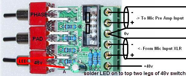
The Go Between is a different PCB to the 99V MB. It just gives you phantom/pad/phase switches and also interfaces with our active DI if you plug them together.
48vPadPhaseDIwiring.jpg


M
 

Latest posts

Back
Top