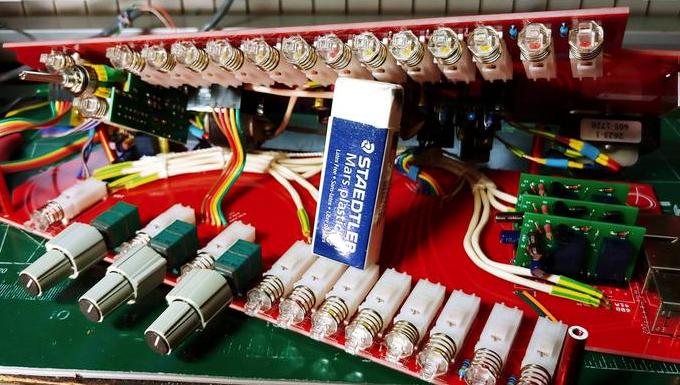
Aux sends and returns in a mixer project- what's your opinion?

GroupDIY Audio Forum

Help Support GroupDIY Audio Forum:

This site may earn a commission from merchant affiliate links, including eBay, Amazon, and others.
Thanks for the questions Newmarket.
I guess ACOM is on the edge connector ? Is there a 'Chassis' connection on that connector too?
Yep and Yessr.
would it tie directly to the metalwork of the chassis ?
In the case of chassis, from the backplane, yes. Agnd from backplane to busbar.  Also the holes trying chassis or agnd to the blank pcb on not in pict since I haven't committed to one yet.
 
The basic purpose of a screen is to catch interference and safely route it direct to safety ground whilst completely avoiding analogue 0V. Last thing you want to do is connect a PCB plane to that.

Cheers

Ian
 
The basic purpose of a screen is to catch interference and safely route it direct to safety ground whilst completely avoiding analogue 0V. Last thing you want to do is connect a PCB plane to that.
Hmm. Thansk Ian. Ok, so are these two statements true:  Agnd pours are a concession to give components that use agnd as low an impedance path to bus as possible, only secondarily used as a shield for audio signal.  Where parts do not need agnd, use something like a chassis pour to catch stray interference.
 
boji said:
Hmm. Thansk Ian. Ok, so are these two statements true:  Agnd pours are a concession to give components that use agnd as low an impedance path to bus as possible, only secondarily used as a shield for audio signal.  Where parts do not need agnd, use something like a chassis pour to catch stray interference.
I would not call Agnd pours a concession but their purpose is to minimise the interaction of ground currents from different parts of the circuit by presenting as low an impedance tp ground as possible. They may also be used to shield audio signals from each other (like a crude screened cable).

As I said, the purpose of a shield is to intercept interference and to do this is really needs to surround the circuit rather than be embedded in it  like a copper pour. So no, I would not use a chassis pour to catch interference. By then it is really too late.

If you have a 4 layer board you could use the outside layer as a chassis pour to act as a screen, have the signals on the two inner layers and use the other output layer as an Agnd pour.

Cheers

Ian

Cheers

Ian
 
I find it a little unusual that the pcb faceplate and edge connector are not parallel.  Do other mixers do this?

To insert the connector you need a perpendicular force to it,  which is angular on the faceplate. Wondering if this creates problems.
 
If you have a 4 layer board you could use the outside layer as a chassis pour to act as a screen, have the signals on the two inner layers and use the other output layer as an Agnd pour.
Thanks Ian for your advice.  In a way it is semi-shielded(?) as a 2 layer, as the outside pours are a mix of acom and dcom with traces inside the card running underneath their respective references. I tried to minimize runs on the outside layer.  It is my hope those pours will sink any stray perpendicular cross channel interference, with the console frame catching the emf from the outside world.

I find it a little unusual that the pcb faceplate and edge connector are not parallel.  Do other mixers do this?
To insert the connector you need a perpendicular force to it,  which is angular on the faceplate. Wondering if this creates problems.

I agree it is less simple that it could have been. So much of this console would have been made easier had I started with the cards and built the frame around them.

The 50pin edge connector does require some pressure for seating, but the 5 risers with pan head screws keep the assembly rigid during down pressure. More problematic was having it sit flush with the frame as you've described, there's some forward angular movement to the faceplate as the card is inserted fully. Regarding the overall length vs faceplate length it is definitely unorthodox; it gets inserted like a foot to a shoe before hitting the connector.  ::)
 
I'd say that if the chassis is 'doing its job' as a screen then you don't need more screening from external interference.
Using ACOM for the pcb plane gives possible impedance benefit, reduces cross talk etc. so I'd go with that.
 
Hello friends.
A question or two if you don't mind, prompted out of an email to Mr. Hardy about his 990c's.
His reply reminded me of the advice some of you have already given but that i've been too intimidated to modify against the skiz I've been referencing:
"If [in your aux schematic ] you are stuck with the 28k value for R10, the 990 will not be as quiet as it could be."

I'm interested to know, why did API choose 47k (group/pgm) & 39k (aux)? Was this due to the amount of channels in their 2448 console? I'm sure 39k was reduced from 47k  for the 5k aux pots. I'm running rather high 20k pots... Does anyone see a significant noise problem keeping the aux bus resistors at 39k?

Also if anyone minds suffering yet another explanation on calculating proper nfb resistors for unbalanced summing I promise to help the next person I catch asking. (>.<)


I do not think 39K (or 47K for that matter )  bus reistors will present a noise problem. If you have 24 channels then the effective bus resistance is 39K/24 = 1625 ohms. The Johnson noise in a resistor this value is approximately -120dBu. Much too small to be important. Its noise will be swamped by the output noise of the 2520 driving the bus.

Handy noise ready reckoner:

150 ohms is -131dBu
1500 ohms is -121dBu
15K ohms is -111dBu

If you double resistance, its noise voltage goes up by 3dB

Cheers

Ian
 
I do not think 39K (or 47K for that matter )  bus reistors will present a noise problem.
Handy noise ready reckoner:
150 ohms is -131dBu
1500 ohms is -121dBu
15K ohms is -111dBu

Thanks Ian, appreciate it!


On my 528 modules there is an extra PC board that is a shield on the right side.  Its a type of extra shield over the A1 mic preamp section.  Its adds an extra shield against adjacent cross talk when the mic pre is turned up to as high as 60 db of gain.  The other parts of the 528 i guess are not so sensitive being at line level or whatever the internal operation level is.  The Agrd pour may be a good idea but depends on what gain the section of the console operates at. 

Some of this old API gear was designed back when tape recorders had a signal to noise ration of 60 to 65 db.  If you added noise reduction like Dolby A you got a 10 db across full band  and 15 db improvement in the high freq band.  So as the digital age came about the noise floor was more  critical. 

Some cross talk might be unnoticed in the old days.  Is that really critical for your needs today?  To do the full analog thing would require you to have outboard reverbs.  The old days a tape recorder was a delay and reverb plate or spring or chamber was the effect.  I myself love the sound of Relabs plug IN of TC 6000 reverb and plan to use it in my session template of protools to interface with the console. 

In headphone mixes for your performers,  what degree of cross talk is noticeable?  You have to be careful not to record the tic of a click into a track but most the time its the headphone acoustic bleed from the phones , not the electrical cross talk that is the issue.  Anyway how will you use Aux's?  Do you plan on adding an actual Reverb Plate, or Older Digital units?  Keeping those units alive can be challenging .   

So how much crosstalk is acceptable and when is the gain in your console being pushed 60 db with a mic pre?  You are using 500 series modules for mic pre 's so you will never be running the routing part of the card with adjacent channels (with mic gains up that high).  I'm not a designer so I don't know whats right but thanks to Abby and PRR and JR and others you get advice.  Do  you have a cross talk  problem that requires that much attention?  When connecting all these various shields and outboard and inboard gear, avoiding loops and such is an absolute must.           


Attachments

  • Old School Shield pour.jpg
    Old School Shield pour.jpg
    117 KB · Views: 30
Wow thanks Fazer for pulling the channel out and showing me that!

Some cross talk might be unnoticed in the old days.  Is that really critical for your needs today?
Good question. I moved on to the aux cards while waiting for the cnc guy to finish my backplane metal. I'm about to jump ship on him as I'm getting tired of missing completion goals...I could use a program manager / life coach at this point. =D
How will you use Aux's?
This short answer is...I don't know yet!  ::)  The long answer is Cue (obviously) and experimentation while I build up tube gear. Add some studio outboard dynamics & EQ essentials as income allows, along with a number of dedicated PC servers for realtime fx processing, modular synth stuff, oddball fx gear / spring verb for project-specific album work.
Do you plan on adding an actual Reverb Plate, or Older Digital units?
I have not given outboard verb much thought due to inexperience with the good stuff. Plugins like Altiverb, Valhalla and Lexicon pcm have been my bread and butter for almost all my work to date.
Do  you have a cross talk  problem that requires that much attention?  When connecting all these various shields and outboard and inboard gear, avoiding loops and such is an absolute must. 
I have yet to get the beast to sum audio yet... :mad:  But yessr, I hear you!  Once I build up an aux card in about two weeks the first thing I'll do is test out some returns with pin 1 connected and disconnected to shield, plugging into different outlets around the shop.
Thanks again Fazer and everybody for all the advice! You had me get fairly obsessive with channel card layout that will hopefully pay off. Per suggestions and warnings from Ian and others, I got into the habit of going a little oldschool, replacing all positive audio traces that would otherwise need vias or span any serious length in the cards with shielded p2p wiring. I believe 12v, 5v and dgnd are about as isolated as possible from signal on a 2 layer board, the only exception being the hpf pcb led.  Fortunately noise has not yet been an issue with bench testing un-racked single channels.  I've moved a neon lamp and cellphone above and around them with no serious interference... Pray for me this scales up, including summing!
 
Rev1, channel 1,  was a bit hairy. 
zF8uBhn.jpg
 
My daw template will require 32 I/o to patch 24 Channels and 2 to 6 sends and 8 stereo fx returns.  This means I can mix old school and use my board to balance and eq and compress with inserts analog .  But that said I’ll still be automating in the computer as well as all the other duties.  And any post production gigs will be ITB for consistency when doing revisions.  Just no way I could give up a daw’s feature set.  Getting my 16tk tape interfaced is in the Q but I haven’t been working as hard as you have my friend.  Just an incredibly amount of work and it looks so professional.
 
Just wanted to say thanks Paolo for the suggestion. After playing with the BK duals, went with the Bourns 51's.  $6ea ain't too bad. 

And you too Fazer! Thank you!
 

Latest posts

Back
Top