Aux sends and returns in a mixer project- what's your opinion?

GroupDIY Audio Forum

Help Support GroupDIY Audio Forum:

This site may earn a commission from merchant affiliate links, including eBay, Amazon, and others.
Newmarket said:
At P&G, at least, tapers were  / are ( It was a while ago I was there)  trimmed manually on the production line - removing ink to get the taper within spec'.
Which made them awfully expensive; acceptable for faders in a £40+k mixer, but not for every pot in them.
In the meantime, silk-screen and ink technology have improved significantly.
 
abbey road d enfer said:
Which made them awfully expensive; acceptable for faders in a £40+k mixer, but not for every pot in them.
In the meantime, silk-screen and ink technology have improved significantly.

Yes - I was thinking faders - which were the main thing.
Rotary CP 'pots' too but IIRC selling mainly to some 'high end' hifi outfits - Krell etc. - who wanted 'impressive' volume pots.
I recall it amused the MD how much they would pay for a large solid aluminium housing on the pot that didn't help in any technical sense.
They faders were indeed a 'premium' pricing option. Standard on high cost mixers becoming optional (vs ALPS ; TKD etc) as price reduced.
Technology wise I am talking mid to late 90s.
Then there is the issue of lubricating the guide rods whilst stopping the lubricant migrating to the tracks - cue Nyebar...
 
Then there is the issue of lubricating the guide rods whilst stopping the lubricant migrating to the tracks - cue Nyebar...
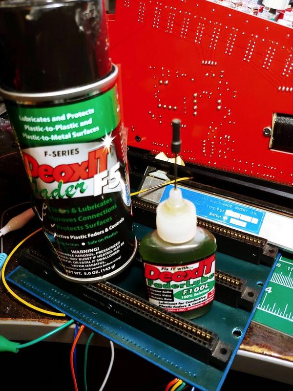
What's your take on the CAIG stuff, Newmarket?

xiG9ZZo.jpg
 
The pot is a Bourns 51CAN-D20-D10L, with is stated as audio taper
Shoot, that's a nice cp pot, Paolo. Not too bad on cost either, but Mouser has a min qty order of 500.  I would have looked for those elsewhere had I not just the other day purchased some BK 1k/10k dual concentrics from CAPI.  I figured the 10k would be useful for returns panning down the road if returns-on-channel gets bothersome.
 
I asked in the brewery about an oddity in the Jensen paper on tx's about polarity, and folk's answers were generous, but it still has me second-guessing myself.  I would not have figured it mattered before, but, since I'm inverting polarity with a ACA, reassure me there's nothing wrong with permanently flipping the secondaries to restore polarity?  :eek:

Thanks!
 
boji said:
, reassure me there's nothing wrong with permanently flipping the secondaries to restore polarity?  :eek:
Alternatively, you could  flip the primary! There may be a tiny (probably just barely measurable) difference in HF response, due to the different capacitive (stray) coupling.
 
boji said:
What's your take on the CAIG stuff, Newmarket?

xiG9ZZo.jpg

I should say that I wasn't involved with fader / pot manufacture myself as I was designing / developing electronics.
But I think the CAIG products you're showing there are applied to the tracks / wipers ?
I was referring to the application of 'damping grease' IIRC ROCOL Kilopoise to the guide rods. There is an issue of this migrating to the tracks (not good) hence use of a 'barrier' product - Nyebar - to inhibit this.

I haven't used the CAIG stuff for faders. But I do have a can of the general CAIG 'DeOxit' spray and I do find it works well for contacts / connectors etc.
 
After having tried many things, I've found that using distilled water and soap is the best way to remove contaminants from fader tracks. Apply with a light brush or Q-tip and wipe. Let dry in warm air (foehn/hair dryer) before re-using.
 
Thanks for the advice guys. If the Deoxit is water soluble, I'll do a comparison test with a light touch.
Maybe F100L for the guides. Honestly the guides need replacing. They're from an early 80's Audioarts Wheatstone 32ch, so they got quite a bit of rock in the roll and dirt in the skirt.  :-*
Hopefully I can avoid using the most tired, as a few have noticeable abrasion grooves on the tracks.
 
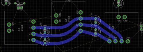
Anyone see a problem with three OPA's sharing two sets of power caps? You're welcome to tell me to stop being lazy and add a third if each need their own, and/or go smaller, etc. Thank you! (caps are 100uF)

9nHSU1D.jpg
 
Probably OK for electrolytics. I might consider separate HF ceramic discs by each, but those OA look pretty close together. You can always put holes in the PCB and not populate them unless needed. 

JR
 
I might consider separate HF ceramic discs by each, but those OA look pretty close together. You can always put holes in the PCB and not populate them unless needed. 

That's a good idea!  Thanks JR.
 
boji said:
Anyone see a problem with three OPA's sharing two sets of power caps? You're welcome to tell me to stop being lazy and add a third if each need their own, and/or go smaller, etc. Thank you! (caps are 100uF)
The electrolytics can be put almost anywhere, not necessarily very close to the DOA's but I would put the ceramics as close as can be.
However you should ensure that the current that return from the loads are properly directed to where they belong.
 
However you should ensure that the current that return from the loads are properly directed to where they belong.
;D Yessir.  Workin' to it!

Do the DOAs already have ceramic bypass caps on board?  I believe some do.
Now that you mention it John12:ax, the GAR 2520's do.  Oh well. At least the pads are there in case of alternatives.
 
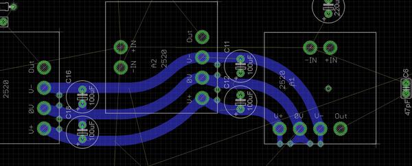
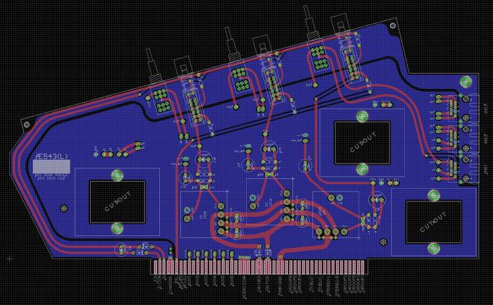
Ok so mostly finished the Aux send card routing. 
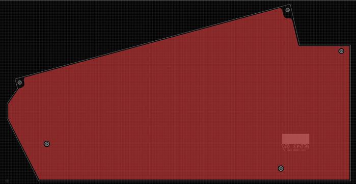
I have quick question on the blank panel that sandwiches it:
I have put a pour across the whole blank PCB, does it matter if it's tied to acom or chassis?  I suspect you'll suggest acom since that just means more copper for the most important com, but I figure asking can't hurt as chassis would work well as a screen and I plan on using fat bus bars for audio.

9D2XuMQ.jpg

xo2FAIw.jpg
 
boji said:
Ok so mostly finished the Aux send card routing. 
I have quick question on the blank panel that sandwiches it:
I have put a pour across the whole blank PCB, does it matter if it's tied to acom or chassis?  I suspect you'll suggest acom since that just means more copper for the most important com, but I figure asking can't hurt as chassis would work well as a screen and I plan on using fat bus bars for audio.

9D2XuMQ.jpg

xo2FAIw.jpg

How would / do the acom / chassis connect to the pcb.
I guess ACOM is on the edge connector ? or a busbar ?
Is there a 'Chassis' connection on that connector too or would it tie directly to the metalwork of the chassis ?
 

Latest posts

Back
Top