Basics...offset triming, and mercury batteries

GroupDIY Audio Forum

Help Support GroupDIY Audio Forum:

This site may earn a commission from merchant affiliate links, including eBay, Amazon, and others.

Freq Band

Well-known member
GDIY Supporter
Joined
Jan 5, 2006
Messages
608
Location
Electra City
Sometimes I need to revisit the basics because I've missed something.

How do you adjust the null trimpot of an opamp that's already "in-circuit" ...in other words, that has active components before it, and after it ?

I suspect you disconnect any signal to the opamp's input, and measure the null directly at it's output pin while adjusting the trimpot (but leaving resistors Rf and Rin in play).
(??)


This particular circuit is a single supply. I've put a 20k offset trim per the datasheet of the (substituted) OP77. The offset shouldn't be much, but I trying to get extra precision.
Powered by a 9v battery.
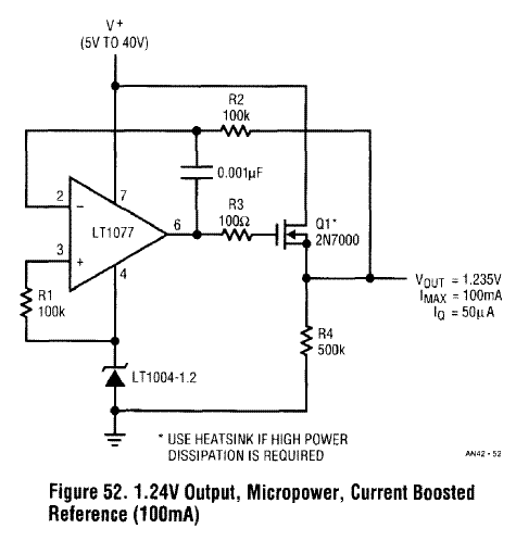
my_op77_1vref.gif


I've tried removing the FET (and added a jumper to complete the feedback loop),
Removing the 500k,
Leaving the Vref device out,
R1 open, then tried R1 to ground.
No changes....I cannot get 0v at the output.

But I still get around 0.4v - 0.6v at the output on my 7-place DMM.

=FB=
 
In fact the whole circuit is about 0.4v high as shown.
I do not get 1.235v...I am getting 1.61v++, even with the trim pot disconnected.
:evil:

The voltage slowly climbs (5 minutes) at power-up from 1.604 to 1.61++...??
Voltage across the Vref is 1.2xxV steady at power-up.
Resistors were screened before being installed, to 0.1%.

Trying 20v regulated power, starts the output at 1.62v and climbs from there.

:evil: :evil:

=FB=
 
Now it starts off even higher at initial power-up.....like I'm "burning in" the last voltage output reading every time I connect and disconnect the battery.
It now starts at 1.63v...then climbs up.
Even with a 100 ohm load to help discharge the only cap.

It's not like I'm "charging the alkaline battery", because even from my regulated bench psu....it is higher each time.

**** me.

=FB=
 
> substituted OP77

The OP77 will NOT work in this circuit.

Look at what the circuit does. It uses the opamp's negative supply pin to juice a 1.2V diode. It has the opamp's "+" input at the same point, and the "-" input follows. Therefore both inputs MUST stay fully functional when sitting AT the chips' negaive supply pin potential.

The OP77 won't do that. It has NPN inptuts, so without even looking at the rest I know the inputs will quit working before they get within 0.5V of the negative pin. The sheet says, for +/-15V supplies, input range is +/-13V min +/-14V typ. So it must work with inputs 2V up from the neg rail, and may work at 1V up (but don't bet the business on this).

The output has three devices PNP NPN NPN to the negative supply pin, so it can't pull down to a volt of the neg pin, which may or may not be enuff to bias the MOSFET.

That circuit is "tricky", does something which may be unique to the LT1077. Chipmakers love to publish such tricks, because it may do something which no other chip can do so well/simply, and it locks-in your business.

They use the LT1077's fairly constant current versus supply voltage to juice the diode, and the LT1077's to-neg-rail input compliance to get the diode voltage compared to the output voltage.

BTW, the dumb old LM324 will "work" here. Supply current changes very little with supply voltage, not enuff to upset the LT1004. Input compliance runs a hair below the neg supply pin. The output can pull very near the neg supply pin. Input offset is a couple mV, but the LT1004's typical spread is more than that (90% may be 1.230V to 1.236V, +/-3mV, +/-4mV at 20uA guaranteed). You could even use a pull-down on the LM324 and eliminate the MOSFET. Slave the three spare amps on the chip to one reference amp, get up to 100mA output.

To offset trim your OP77: first bring the inputs up into their working range. Easiest may be to use >+15V power, apply a 9V battery to the + input, strap - input to output, then bridge a floating meter from the battery to the output. Trim for zero.

However the untrimmed offset of a OP77 is OTOO 5 microVolts, and I doubt you can better than on the average testbench. Nor that 5uV amp error matters against 4mV diode tolerance.
 
It's frustrating to a novice when companies say OpAmp X is a direct replacement for OpAmp Y.

Thanks PRR for rescuing me from more hair pulling.
Is this why old engineers are bald?
(see newly inspired quote below)

Strange the "burned-in" voltage at each measurement.
Did I cook the chip?

=FB=
 
PRR gave you a good detailed explanation. I'm here to give you the datasheet information. The lt1077 is rated for single supply, which means that it can come very close to ground. The op77 can barely get within 1v of ground with practically no load at all. Once the non-single supply/rail-rail opamp gets close to the rail like that it's not a happy camper.

Look for Vo (output voltage swing) on the datasheets. For the OP77 you get a couple different numbers per detail table. It gives you RL which is the load at which it was tested. Some datasheets tell you these things, some don't.

The Lt1007 datasheet gives you a Low and High set of numbers. Low is around .7mV with a 2k load. High is around 3.9v with a 2k load and 5v + rail.


Anyway, chances are that the voltage you saw was the best the opamp could do in the circuit as PRR pointed out.

And always, always doublecheck everything you can compare between opamps that are supposed to be replacements.

:thumb:
 
> Look for Vo (output voltage swing) on the datasheets.

In this case, that's a side-problem. The MOSFET (ass-uming not subbed with a JFET) means the chip output does not have to swing all the way to its neg rail. The MOSFET gate will typically sit a couple volts higher than its source, which is where 'bout everything else is sitting, near 1.23V.

The killer problem is inputs sitting at neg rail. That's real tricky. Many chips will have semi-constant supply current, semi-regulating diode current. Not so many chips will work with inputs at neg rail. It is like you putting your eyes on the floor. I won't try. My dogs are built lower and can twist their heads, see under a door-crack pretty good.

Vout, combined with 1.23V and the MOSFET offset, may explain the 1.63V he's seeing. No idea why it rises at every turn-on. Moot, since the circuit won't do what he wants in this configuration.

> companies say OpAmp X is a direct replacement for OpAmp Y.

Does it say that? Usually they only say that when it is the SAME circuit stolen/licensed from the other, built on same or superior process. Yes, the OP77 "can" do most of the non-tricky things we used to do with LT1077, better. However it does not have to-neg-rail inputs, and it sucks 1mA power against 0.060mA for the LT1077. Not really close! National actually claims: "The OP-77 is a direct or upgrade replacement for the OP-07, 05, 725, or 108A op amps." No mention of '1077.

If these are the parts you have.... abandon the tricky way to feed the diode though the chip which is buffering it. Use 500K from raw supply. The LT1004 has pretty good rejection 20uA-50uA, your likely range of raw supply. Now feed the OP77 with raw supply and ground. That sets the '77 inputs up at +1.23V. This is illegal under Max specs, but within Typ specs, so it will "probably" work. Not trustworthy for a rocket ship, good-enough for a bench reference which you will test-test-test before giving it any degree of trust.

Still think the LM324 will perform the same stupid stunt, with a barely significant rise in error window. Partly from '324 slop, partly from running the diode higher up on its current-curve. (The LT1077 current happens to fall on the flattest part of the LT1004's curve.)
 
I appreciate the explanations, greatly.

I am on a quest to find and build a suitable replacement for a mercury battery cell, for rehabbing an elderly JRL voltage potentiometer.
...preferably using components I already have.

The potentiometer uses a saturated cell as a reference - in order to adjust the mercury battery's voltage of 1.345v...down to exactly 1.00000v. Then the battery becomes the 1v usable reference. So it has to be stable, and noise-free.

Old battery.....
Mallory RM42R T2
Mercury-Zinc
1.345v
14000 mAh


I've probably posted this non-audio quest of mine too many times on this audio forum.
Does anybody know of a suitable forum concerning 1950/60's era DC standards ?

(text from the equipment's manual)....

"" The mercury cell is thermally lagged to maintain a voltage stability of 0.0005% / 0.5 hour (5ppm / 0.5 hour). This stability is for extremes of temperature variation in a normal operating environment. Where highest accuracy is required, calibration should be checked at the beginning of each new measurement. To maintain stability when the (voltage divider) is disconnected, provide a constant battery load by connecting a 100k resistor across the (voltage divider) load. ""

=FB=
 
[quote author="Freq Band"]I am on a quest to find and build a suitable replacement for a mercury battery cell, for rehabbing an elderly JRL voltage potentiometer.
...preferably using components I already have.[/quote]
It would be useful to know more about the kind of specs you are trying to arrive at. How much accuracy (long-term, vs temperature) do you need for your application? How stable is your environment (temperature, supply variations, load variations)? What's the load current?

Considering that the Volt is not defined in terms of Mercury cells (ie: it's not a primary standard), it's likely that HgO cells will drift from their nominal value, either over time, temperature or between batches. Have you Googled around to find the average/expected accuracy for Mercury cells, either in general or in your specific configuration?

You are likely not the first to encounter this problem. Is this any help?

JD 'you can't get what you want till you know what you want' B.
 
Maybe a zener-follower would be low enough noise for this?

In this case, that's a side-problem. The MOSFET (ass-uming not subbed with a JFET) means the chip output does not have to swing all the way to its neg rail. The MOSFET gate will typically sit a couple volts higher than its source, which is where 'bout everything else is sitting, near 1.23V.

The killer problem is inputs sitting at neg rail. That's real tricky. Many chips will have semi-constant supply current, semi-regulating diode current. Not so many chips will work with inputs at neg rail. It is like you putting your eyes on the floor. I won't try. My dogs are built lower and can twist their heads, see under a door-crack pretty good.

Vout, combined with 1.23V and the MOSFET offset, may explain the 1.63V he's seeing. No idea why it rises at every turn-on. Moot, since the circuit won't do what he wants in this configuration.


PRR: yes, I meant to mention inputs as well but I generally group single supply and rail-rail opamps as BOTH input and output swing as described. I tend to forget that other folks can't read my mind when it comes to this stuff.. :green:
 
It would be useful to know more about the kind of specs you are trying to arrive at. How much accuracy (long-term, vs temperature) do you need for your application?
"" The mercury cell is thermally lagged to maintain a voltage stability of 0.0005% / 0.5 hour (5ppm / 0.5 hour). ""
The voltage does not need to be precise, as it is always trimmed down to 1v....but it needs to be steady....anywhere around 1.2 to 1.4v.


load variations ?
This is difficult for me to answer.
The old battery was only engaged into use for 5-10 seconds for each measurement, through a series of trimming resistors to reduce it's voltage by 0.345v...to achieve 1v as read on a null meter. The trim network for that is beyond my ability to calculate the current load.
Old mercury battery was a 14000 mAh cell, and is supposed to last a year, with a 100k resistor across it's terminals when not "in use".


How stable is your environment / temperature?
The battery supply is housed inside a plastic housing, inside the Potentiometer...which gives it "thermal lag" from temperature changes outside the unit. Consider median temperature to be 23` C.

supply variations?
All battery operated, which is why I was looking at V reference chip circuits that are unaffected by battery supply variations.

You are likely not the first to encounter this problem. Is this(link) any help?

Yes, I've seen that. The silver oxide batteries "may" work, but only last for a few months. Yes, you would think other people would have come across this situation...:? ....but I cannot find a suitable solution. That is why I'm searching datasheets for circuits. I am not a circuit designer yet, but I am slowly loosing my hair.

=FB=
 
[quote author="Freq Band"]
It would be useful to know more about the kind of specs you are trying to arrive at. How much accuracy (long-term, vs temperature) do you need for your application?
"" The mercury cell is thermally lagged to maintain a voltage stability of 0.0005% / 0.5 hour (5ppm / 0.5 hour). ""[/quote]
That's the (current) machine spec, with the obsoleted battery. Could you tell a bit more about the bigger picture? What does the machine do? What kind of performance do you need? How much space do you have for a fix? There are several ways to get a reference with good stability, the trick is to not make it any more expensive (or large, or cumbersome) than necessary.

[quote author="Freq Band"]The voltage does not need to be precise, as it is always trimmed down to 1v....but it needs to be steady....anywhere around 1.2 to 1.4v.[/quote]
Trimming would imply that you have something with higher accuracy than the battery. What do you use to calibrate this trim?

JD 'you've got questions, we've got more questions' B.
 
BTW, there is a JRL PVP1000 on eBay today, Item number: 230277960489 also Numero oggetto: 260267009017

One of Julie's pot patents: http://www.google.com/patents?id=W-ZjAAAAEBAJ&dq=3416084

>> Quote: How stable is your environment / temperature?
> Consider median temperature to be 23` C.


But how stable? 23.0-23.1 all the time? 20 today and 26 tomorrow?

IAC: you are over-thinking. The LT1004 plus a poorly regulated power supply and resistor is pretty clearly intended as a Mercury Replacement. A Mercury cell used as a reference will be worked at low current, OTOO the current that the LT1004 can regulate. A 9V battery, a 47K resistor, and the LT1004 should give a VERY stable voltage. Something like page 6 of the LT1004 datasheet, except since you don't know the current required I've upped the idle current 10X.

> The trim network for that is beyond my ability to calculate the current load.

Maybe someone else could?
 
[quote author="PRR"]>> Quote: How stable is your environment / temperature?
> Consider median temperature to be 23` C.


But how stable? 23.0-23.1 all the time? 20 today and 26 tomorrow? [/quote]
Yup. Or, as in my 'lab', 22.0 all day except when it's morning and cloudless and my eastward-facing windows start acting as a greenhouse.

[quote author="PRR"]A 9V battery, a 47K resistor, and the LT1004 should give a VERY stable voltage. Something like page 6 of the LT1004 datasheet, except since you don't know the current required I've upped the idle current 10X. [/quote]
Wouldn't that be ~110mV low (1.235V vs 1.345V)? Then again, the (unknown) range of the trim circuit may be wide enough to cover that. It'll also have a thermal time constant of more than 5ppm/0.5 hour, but something as simple as a small cardboard box stuffed with cotton/rockwool with the ref diode in the middle may be enough to fix that.

[Should you go for thermal isolation: remember that copper wire is an excellent conductor of not only current but also heat. Crystal ovens use the thinnest copper/steel/invar wire they can get away with. Keep in mind that the thinner the wire, the higher the resistance]

JDB.
 
JDbaker said:
Could you tell a bit more about the bigger picture? What does the machine do?

PRR said:
> (FB said) The trim network for that is beyond my ability to calculate the current load.

Maybe someone else could?

Perhaps these two pages from the manual may help:

http://i5.photobucket.com/albums/y177/Midiot/JRL_mercury_trim.jpg
http://i5.photobucket.com/albums/y177/Midiot/DSCN3397.jpg

Yes JD, there is a sealed plastic battery compartment inside the unit , that I can fill with foam, rockwool, etc.
Simple is good. Battery, resistor, and Vref...if that's all I need.

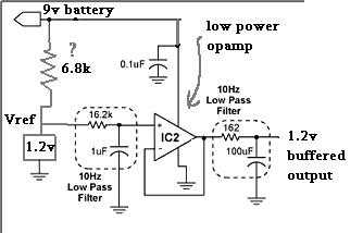
In the mean time, I whipped this up in an hour, working...
(though the filters are sucking current, no?)

OP77F
1000 ohm load = 0.96mA
100 ohm load = 4.5 mA
Vref is an AD589J !!

my_buffered_1v.gif


=FB=
 
> the Volt is not defined in terms of Mercury cells (ie: it's not a primary standard)

That bothered me too.

This is (was) THE voltage standard:

085-014-004.jpg


The first legal unit of voltage for the United States was based on the Clark cell, developed by Latimer Clark in 1872, with its output assigned a value of 1.434 international volts by the 1893 International Electric Congress. Public Law 105, passed by the U.S. Congress in 1894, made this the legal standard of voltage in the U.S. During the years between 1893 and 1905, the standard cell devised by Edward Weston was found to have many advantages over the Clark cell. The Weston cell consists of a cadmium amalgam anode and a mercury-mercurous sulfate cathode with a saturated cadmium sulfate solution as the electrolyte. In 1908, at the London International Conference on Electrical Units and Standards, the Weston cell was officially adopted for maintaining the volt. After 1908, only Weston cells were used for maintaining the national standard in the United States.

We now favor a "Josephson effect" gizmo. Nobody here could care if the reference is electochemical or quantum.

In either case: you need to draw Dead Zero current from your reference.

What potentiometers like the Julie do, is start with a semi-stable higher voltage. Divide that down to 1.01830V. (Julie's 1.017924V seems to reflect a correction between 20 deg C standard Weston cell temp and an average lab temp.) Now test the divided 1.017924V against the Standard Cell. If ANY current flows, trim some more, until the galvanometer shows NO deflection when the compare button is pressed.

Now that you have a fairly solid voltage, you can divide that down to any lower voltage needed. (How you get precise resistor ratios is a different problem, but one that Loeb Julie chewed very well. Before Loeb they tried long resistance wires and sharp yardsticks, with obvious errors of wire diameter, alloy variation, and errors of length measurement.)

The PVP uses a large Mercury cell, flowing obviously 0.017V/1700R= 10uA, to excite the bridge. BTW, this battery runs throughout a measurement. Replacing this seems to be today's problem.

The stock resistors want a Mercury battery 219.60mV to 237.64mV above the Weston cell voltage, 1.237V to 1.255V. There are several variants of Mercury battery; this is not the one which gives 1.3V. There is a ~~1.25V version. LT1004 at 100uA and 25C is 1.231-1.239. So it may need to be fudged. Being a Ford mechanic, I'd tack 3M3 across the 375K. However, at this accuracy, the contaminants in my solder cause relatively huge errors.

And when you face the facts: this thing is useless without a Weston Cell. Where do you get one of those today?
 
..this thing is useless without a Weston Cell. Where do you get one of those today?

I've got two JRL standard cell oven(s) coming to my doorstep soon.
http://i236.photobucket.com/albums/ff225/pa202203/S1050223.jpg
They are saturated cells,
and hopefully they are still viable,
and hopefully I may get them calibrated,
and hopefully I won't go broke chasing my 1volt hobby.

Option two is to get my HP 735a DC transfer standard.. calibrated, and use that instead.

I'm going backwards in time, rather than forwards.
Strangely, I find this stuff fascinating.

=FB=

Next up...that superconductor standard you mentioned. (yyyyyright)
 
> the filters are sucking current, no?

100uFd is probably an electrolytic and surely a poor idea.

The 1uFd's leakage is a compromise with the resistor and the opamp's input current. This can be calculated.

It is not clear to me why you need filters. The PVP calibration uses a slow mechanical device. And possibly sticky. The 1/f noise in mercury and Weston is mostly integrated-out, and may be useful to dislodge movement-stick on very fine currents.

> I've got two JRL standard cell oven(s) coming...

:shock: :shock:
.
 
OK, the mercury-replacement only has to be stable enough that you don't have to calibrate it against the Weston every coupla minutes.

And in fact, for hobbyist activity, you "can" tolerate (maybe enjoy) frequent re-calibration, more than a busy calibration lab could stand.

IF my math is correct (I tossed it off without groking all of Julie's tricks), then the "mercury cell" should be ~~1.246V, and the LT1004 is ~~~1.235, and the AD589J is 1.235. So we need 0.011V up, on average. However we could need 0.046V up or 0.004V down. If we use a trim-amp, we also have to allow for the amp's offset, which could be 0.002V or 0.000,04V. We do NOT want to "trim" the reference with an opamp's offset trim, because drift is minimized at zero offset and we don't want to add drift. So we may want a gain of 0.995 to 1.050. That's not easy; fortunately we "know" if gain is higher or lower than unity once we bias-up a specific reference part and burn it for a few weeks.

Usually, a secondary reference has a long warm-up time, and is left running night and day. That's why you had the huge merc-cell for a mere 10uA drain. So we want a system which can be left on for a while, say a year. This could be a D-cell at 1mA or a 9V at 20uA. We need 10uA for the potentiometer. Can we do a reference and a trim-amp in another 10uA? That is tough. The LT1077 is 60uA. Can we do a 1.246V reference under a 1.56V D-cell? That's tough. Two or four D-cells is not a large investment.

Ultra-precision is not my gig. I'm a Ford mechanic, I have a short-handle 20-pound hammer which works on most of my problems. I hope you find a real precision-head.

I'd go with two good D-cells and that LT1004 diode through a 75K resistor. See if the PVP can be trimmed-up so you see 1.018V at the "STD CELL +" jack while holding the "High" button (or read the wiper of the R3 30-pos pot-switch). If so (if the PVP has enough trim-range to bring your LT1004 to Wesson Voltage), then let the D-cells and LT1004s run for burn-in while you attend to Weston Cell cleaning and rough-checks (do they seem to be 1.018V? Is the oven holding a good temp?)

Once it's all set, do the calibration, do some practice runs, and re-do the calibration. Do lunch and check again. How long can the 2-D+LT1004 reference run before it gets out of calibration? For hobbyist use, "many minutes" is plenty good enough. (If you have a stack of work to ship-out today, a longer work-time between calibrations would be nice.)

I'm not sure how far I'd go to get the Westons calibrated. This WAS the Official Reference. If the chemistry is right, the voltage IS right. And the chemistry is right because the guys who made these things were serious geeks, and surely destroyed any dubious cells at birth.

Having two cells is a Problem. If they agree, OK. But when you learn to measure very fine, they are sure to be different. And if they differ enough to matter (you DO need to set a resolution goal), which one is right? With three, you cast-out the odd one. The National Labs held banks of a dozen or so.
 
I appreciate the time you invested.

I did not plan on getting 2 ovenized standards. The first one was cheap, and looked a bit beat-up on the ebay pics. but I bought it anyways**. Then another one was listed, in better looking shape. So I bought that too, thinking I could use the first for spare parts, if it came to that.


** How one of these would ever get beat'up and the wooden corners worn down, is beyond me. Maybe someone took their voltage standards on tour.

Plus, why am I not surprised the ebay seller didn't show a pic of this side of the unit....:shock:
http://i5.photobucket.com/albums/y177/Midiot/DSCN3403.jpg

The ugly one arrived today. No leaking cadmium.
I think it needs to be on for a few days to stabilize........quick initial check (for 1 second) of the three internal cells using my cal'd HP 3457a DMM (10meg) says....
1.0175xx volts
1.0176xx volts
1.0174xx volts
(target = 1.017924)

BTW here's Linear's collection of Vref circuits.
and
another one (see page 9, fig 16)

I've decided to order some parts (digikey)
LTC1049C ...(chopper amp)
LTC1052C... (chopper amp)
TLC2654A... (chopper amp)
TLC2652A...(chopper amp)
LT1495C...(IN/OUT R to R low power opamp)
LT1077AC
LT1634AC...(prec 1.25v Vref)

But these are not necessarily for the circuits we're discussing.
I'll try the easiest first, like you described.

or...

So we need 0.011V up, on average. However we could need 0.046V up or 0.004V down.
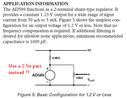
2_5v_variable_ref.png
 
Back
Top