BC550C CCS - ring of two vs. led bias

GroupDIY Audio Forum

Help Support GroupDIY Audio Forum:

This site may earn a commission from merchant affiliate links, including eBay, Amazon, and others.

FunkyB

Member
Joined
Jun 18, 2010
Messages
14
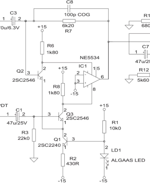
Lets say you want to design a low noise, high z, thermally stable ccs, capable of delivering 400uA to 5mA. (e.g. to be used in a long tailed input pair of an opamp, or to current bias the bias diodes in a class ab emitter follower output stage.)

I still see both of these circuits being used. However nowadays the cost of a bc550c is no more than that of an AlGaAs led. And the pcb space these circuits take up is about the same (both in smd and th).

BC550-C-CCS.jpg


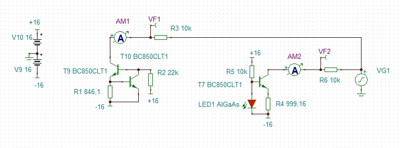
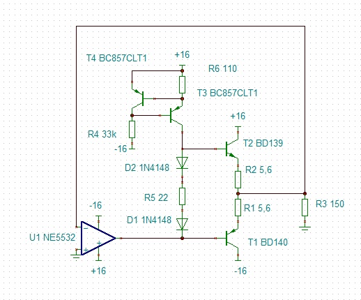
I'm under the impression that -of these two circuits- the ring of two has the highest (dynamic) output impedance across all frequencies, and the best thermal tracking.

Are these assumptions correct? And if so, then why would anyone still use the led circuit? Will the led circuit have any advantage over the ring of two on any terrain?
 
Back in the 80s I used a LED for a low voltage reference inside an analog delay line kit... No particular benefit, but I did it because I could... Back in the 70s LEDs were much too expensive to use casually, now they are dirt cheap.

JR
 
Instinctively I would assume the two transistor circuit is superior. The impedance of the regulating transistor will depend on how constant the current at the base is. With the LED circuit, I suspect the voltage will drift quite a bit up and down as the base current increases / decreases. That doesn't happen nearly as much with the two transistor circuit because if you imagine an infinitely small increase in current through the pass transistor, that will cause the voltage across the collector resistor to increase which will turn on the regulating transistor and divert base current which and counter the infinitely small increase in pass transistor current. The LED is just a shunt regulator where the two transistor circuit is employing an active element to regulate. Clearly the two transistor circuit is superior.

The only thing I can think of is that maybe something special happens with the LED circuit under overload conditions like it prevents latch-up or some such. But I doubt it. I don't see how it could. Just thinking out-loud.

I've never messed around with making discrete amps but just from looking at datasheets the prevailing topology for the past 40 years is pretty clear and it's not what you're exploring. Normally you see a JFET in series with two diodes to make a precision voltage reference and then that's used to set the base current on a network of current mirrors. That is superior for one obvious reason which is that the current will be mostly the same regardless of supply voltage. You could run your amp on +-24V or +-12V and the currents will be mostly the same and any resistors in the circuit will have a consistent voltage across them which makes the whole thing a lot more predictable.

If this is a design exercise and you're trying to create the most well regulated, fastest, most powerful and amazing amp the world as ever seen, I would say too things. First, unless you're doing something radically different, that's kinda boring. Second, what you'll end up with is a high frequency oscillator with a tendency to burn out whatever it's connected to.
 
Thank you very much for your answers.

My goal is not to develop a new opamp. Only to add a low noise transistor pair to a NE5534. You can get to the collectors of the integrated long tailed pair via the comp/bal pins. There's even an app note by OEP transformers that shows this.
This is also an example of people using a led to set voltage to the base instead of using a ring of two circuit.

OEP-app-note.jpg


Another usage for the ccs would be to both bias a diode string (like shown below) and at the same time, bias the (asymmetric) output stage of the 5532 in class a.

Buffered-5532.jpg
 
I think people frequently do things just to show how clever they are or that something is possible. I know I do. That is a worthwhile exercise. Understanding these things might be the key to solving a completely different problem. But if it's just a clever exercise, you should treat it as such - just an exercise. That first circuit that uses the bal / comp pins as inputs looks a lot like someone was showing how clever they are (and it is clever).

There are two classifications of "pro audio" circuits that I personally think deserve the effort to actually build:

One class are circuits that are classic designs or more specifically the parts of those circuits that can possibly have a characteristic sound. A good example of this is the Urei 1176 compressor. The JFET attenuation element and side-chain make a fast limiter that is a classic design that has a characteristic sound (as do dynamics processors in general). I think there is a lot of merit in reproducing these circuits so that mortals can enjoy and really use these devices at a reasonable price. Although if someone is going to implement a classic design, I think it is important to implement the parts of the circuit that impart the characteristic sound as faithfully as possible. Otherwise, I think it sort of defeats the point. These circuits are imperfect and that is what matters. Making a "better" 1176 is an oxymoron.

The other class are circuits that are simply the best circuit for whatever it is that you're trying to do (or if you're on a budget then maybe the best circuit you can make with the parts that you have access to for a reasonable price). So if you're trying to make a low noise circuit, then you should just make whatever circuit is known to have the lowest noise. At this point, for a mic pre that problem is pretty much solved. The CFIA topology is clearly the winner when it comes to low noise and low distorition at different gain levels. This is the circuit used in THAT 1510 / 1570 chips and many, if not most, modern conventional mixers like those of Mackie and Berhringer and so on.

I'm not really sure what the point of the circuit is that you're exploring. Again, as an exercise, I like to fiddle with such things. But at the end of the day, it's just that - fiddling. If you are trying to build something that you're going to actually use, then I'm not sure I would invest too much time in a circuit like this. Once you get to the noise levels of CIFA which has an EIN of lower than 120dB at even low gain, that's pretty good enough as far as noise goes.
 
It is the nature of design engineers to want to constantly one-up or improve upon past designs. I know, not only have I designed my share of circuitry, but I also managed an engineering group full of design engineers.

The work part of managing design engineers is keeping them from reinventing every wheel that comes along when we already have very round wheels we can reuse. Its a struggle and you have to give the most creative engineers a few wins, to keep them happy. While not piss off the bosses by wasting time and money on already solved problems.

===

For most DIY projects this is just a form of mental masturbation, so like that sounds just do whatever feels good to you.

JR
 
Last edited:

Latest posts

Back
Top