Behringer ADA8000 modifications..

GroupDIY Audio Forum

Help Support GroupDIY Audio Forum:

This site may earn a commission from merchant affiliate links, including eBay, Amazon, and others.
Ok, here are some more test results. Behringer is the master clock, and my EMU 1212 is slaved to it.

I ran them at 24 bit, 48kHz...
http://www.mikerelay.com/test2/24_bit.htm

I also tried running some tests having my sound card and the Behringer at the same sampling frequency but not slaved, and I got some interesting results.

http://www.mikerelay.com/test2/clocking.htm

Sorry about the labeling.. I mean MC3079 and TL074. It's late...
 
Thanks Mike,

It seems that the emu DA part was masking most of the specs for the ADA8K

About the no clocked test, it shows clearly the artifacts because the jitter.
About the clocked versions, are you clocking the emu using the Wordclock out for the ADA8K , or the adat out? If you used adat, using the wordclock will have another little improvement, adat sync have too much jitter, more than spdif or Aes-EBU.

Best Regards,

Synthi
 
[quote author="synthi"]About the clocked versions, are you clocking the emu using the Wordclock out for the ADA8K , or the adat out?[/quote]

I am only using the ADAT out. I'm planning to buy the sync card that EMU makes for my system, and try it all again..

-mike
 
Yeah, I didn't look back, to see how I stated, it, but I think I used the word, nasty to describe the results of unclocked.. But you know, I never have seen the frequency response.


You know, it's interesting a tool like this in the right hands will tend to shatter some of the long debates over things like digital cables sounding better and such.. heh..

But no, really, I can certainly tell the differences in-between opamps. say a 5532 and a 2134, but, when you listen to something like the 8kup against the avocet and the lavry, you go Hmm...

Technology is getting cheaper..
 
[quote author="mike_relay"]

I'll post some pictures. I made the opamp "swappable." :thumb:[/quote]

Please can you explain that? I`m about to mod mine...

Thanks!

Sytnhi
 
[quote author="synthi"][quote author="mike_relay"]

I'll post some pictures. I made the opamp "swappable." :thumb:[/quote]

Please can you explain that? I`m about to mod mine...[/quote]

My best guess is that he hacked a DIP socket onto it.

-dave
 
[quote author="synthi"]Yes.. but how!!??[/quote]

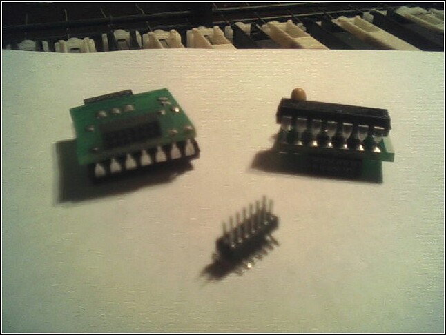
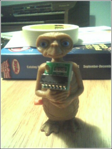
I don't deserve too much credit.. I scavenged some stuff at work. we actually had some pcbs with 33079s already on them . They were part of a pressure measuring device that goes up in a weather balloon. I just had to remove some components and jumper a couple of things.

I don't have a digital camera handy, so I used my phone... hence the crappy picture.

I soldered the piece in the middle to the board, and then the pcb mounts on that.. with the L shaped connecto (the blurry black thing.. if you look closer, you can see the holes.

I'll try to get some better pictures.

33079.jpg


I only did this for the input. There isn't enough space in the output section.
 
I finally picked one of these guys up with the intention of picking up a couple more if they are all they're hyped up to be. I'm ready to do some diggin' and some modding.

The output seems rather straight forward to change to a MC33079, but I'm not too worried about that right now. The input A/D is what I'm itching to change out.

Has anybody done any successfull bypassing of the mic pre junk? Like most folks around here, I just need a solid line level input A/D. Getting rid of the line amp too would be fine by me.

I really like the idea of a simple transformer input straight into the A/D. Obviously it'd have to be a nice match for it all to work out, but it would be sweet. Unfortunately I'm woefully green at all this DIY stuff still and don't know how to proceed any further. I'd be happy to buy and test some transformers, but don't know what I'm looking for. Any tips would be greatly appreciated.

What other input ideas have come about or worked out so far?

-=Jeff Merkel=-
[email protected]
 
[quote author="jeff8houses"]
Has anybody done any successfull bypassing of the mic pre junk?

I really like the idea of a simple transformer input straight into the A/D. [/quote]
The mic-pre junk is already very pretty simple but removal of caps and return it to a line level only thing might offer something.
Change of op-amp could be the biggest change.

Yes the trafo straight into the A/D could be a winner but you may need a little protection to the AD for over voltage.
How this is done could be the biggest secret weapon about.
I've said too much already.
oops
:roll:
 
I seem to recall the application notes from WaveFront said something about this and the B application look pretty close to that so ...
it is likely there is something diode related in there.

I was thinking a little more ...
:shock:

shut up Kev
 
no not me on this one ... I'm too busy

it is something others have talked about and not necessarily in relation to the ADA80000
but is something that is here at the LAB
just two ideas being brought together
 
question to those who have looked at the schematic cause i cant find it in the Manual i have...

does the line input bypass the built in preamp of the ada 8000?
one better would be if i could disable onboard pre's and still use xlr's.

any idea?

i could just go xlr out of my pre then to 1/4 if the line bypassed the pre and went straight to a/d right?


sorry, if kev reads this he knows im on a continous a/d d/a question loop :wink:
 
The only thing I can think of is when we mentioned making a transformer-based A to D based upon the idea of K & K's D/A Lundahl-based converter kits. It came up and then it quickly went away again.

I did some poking around the Burr-Brown section of TI and found some new converter chips out. There is a four-channel A/D chip, the PCM4204, that can do DSD as well as PCM out. I wouldn't touch the DSD stuff right now, though. It needs support in the signal chain that goes well beyond the A/D.

To make a long story short, this chip can do four channels of A/D, and it has serial outs for the PCM data. I'm wondering if this can route straight to, say, an AES/EBU chip or something similar for going to a soundcard. Clocking then becomes the single biggest problem, and I'll bet we can find a solution to that one.

Here's a link to the chip's site: http://focus.ti.com/docs/prod/folders/print/pcm4204.html

This isn't the only one available. I just picked it because it's already four channels. All of the others were either one or two only.
 
does the line input bypass the built in preamp of the ada 8000?

nope :sad: the line inputs are atenuated and then goes to the mic preamp...

could just go xlr out of my pre then to 1/4 if the line bypassed the pre and went straight to a/d right?

I`d like to know that... :cool:

synthi
 
[quote author="asm"]question to those who have looked at the schematic cause i cant find it in the Manual i have...
[/quote]

http://www.gyraf.dk/schematics/Behringer_ada8000_analouge.PDF

http://www.profusionplc.com/static/images/data%20sheets/al1101.pdf
look to page 6 & 7

The AD requires a differential signal of 4 v PtoP for both pos and neg inputs.

Analog Inputs
The AL1101 inputs are self-biased to the MID potential. Input signals larger than maximum
levels (+/-4V differential) but smaller than the supply rails are output limited to maximum
positive and negative levels in the digital section (7f f f f fH and 800000H respectively).

Reference and MID
The differential potential between the REF+ and REF- pins (connected to 5V and GND
respectively) determines the amount of charge that is added to or removed from the modulator?s
first stage during each input sample period (64Fs). It is very important that REF+ is well
bypassed to REF- (.1µF ceramic as close as possible to pins) to remove the unwanted effects of
high frequency noise.
The MID potential is developed on chip (VA/2 volts) and is used to bias the internal amplifiers in
the modulator, and to provide a reference which determines the polarity of the modulator
output. It requires a .1µF bypass to GND at the pin. No load current should be taken from the
MID pin.

you need to look at the diagram to see what is meant here ... look for the pin marked MID.

You will see that on the main PCB of the ADA80000 is practicaly the WaveFront circuit as it appears in the app note.
This does provide the possiblity of bypassing the Mic-pre bits.


What I find more interesting is the opto encoder and decoder pair.
Check the definitions of ADAT format/type
The format pins are summarized in the Formats table. The AL1401A provides support for both
the ADAT Type I format (16-bit) and the ADAT Type II format (20-bit).

Even though the chips may support 24 bit ...
The AL1401A OptoGen? interface has been designed for ease of use and flexibility in systems
designed to interface to the ADAT protocol. It supports both left and right justified 16, 18, 20,
22 and 24-bit data formats for ease of integration into existing devices as well as new devices.
These formats allow it to operate in parallel with many standard DACs.

There is even talk of MIDI and Timecode data. Doesn't say what sort of time code data and it ma only be Alesis Adat time code.
BUT
what we don't know is how each manufacturer sets up things like, the MODE switches.

This also rings true for the Crystal Labs converters and some of the hidden features in their chips.
http://www.digitalaudio.dk/adda_2408.htm

Psycho acoustic dither selectable for A/D and D/D inputs to 16, 18, and 20bit
There are AES papers on this Psycho acoustic dither stuff.

complicated isn't it
 
Back
Top