[BUILD] 1176 Rev A - Back to the beginning...

GroupDIY Audio Forum

Help Support GroupDIY Audio Forum:

This site may earn a commission from merchant affiliate links, including eBay, Amazon, and others.
Hairball Audio said:
AC Impedance and DC resistance are two different thanks. Dc resistance will tell you if there is a break in the coil.

The DC resistances are about:

1-4: 50Ω
5-8: 12Ω

Mike

Thank you so much Mike !
This helps a lot.
1-4 is 51,2 Ohm and 5-8 is 13,1 Ohm.
So the fault must be on other side.
I will get it, I'm sure that I will find the issue.
Thanks for the help.
 
I am having some trouble getting my 1.2.5 rev A going.  I have followed the troubleshooting guide and am getting correct AC voltages at all test points except the Output Transformer Brown, where I am getting 7.82VAC and across the output pin 2 and 3 I am getting 0.03VAC. 

I am getting all DC voltages as noted on the voltage sheet (+/- 5%) except at Q4 where I am getting 13.67VDC and 4.44VDC (Instead of the 6.6VDC noted on the voltage sheet).  I have checked all resistors and caps in the line amp and have found no errors. 

Any insight into what could possibly be wrong would be amazing.  I feel like at this point I am just spinning my wheels.


Thanks,

Jeff
 
jbmacdo3 said:
I am having some trouble getting my 1.2.5 rev A going.  I have followed the troubleshooting guide and am getting correct AC voltages at all test points except the Output Transformer Brown, where I am getting 7.82VAC and across the output pin 2 and 3 I am getting 0.03VAC. 

I am getting all DC voltages as noted on the voltage sheet (+/- 5%) except at Q4 where I am getting 13.67VDC and 4.44VDC (Instead of the 6.6VDC noted on the voltage sheet).  I have checked all resistors and caps in the line amp and have found no errors. 

Any insight into what could possibly be wrong would be amazing.  I feel like at this point I am just spinning my wheels.


Thanks,

Jeff

Yellow and orange tied together?

Double check all output transformer soldering.
 
Thanks for the quick reply Mike.

The yellow and orange are tied together.  I just reflowed the output tfr connections to the pcb earlier this evening and the wire colours match the pcb designations.  I am still getting the same readings. 

Is there anyway to check the transformer to see if that might be the issue? 
 
jbmacdo3 said:
Thanks for the quick reply Mike.

The yellow and orange are tied together.  I just reflowed the output tfr connections to the pcb earlier this evening and the wire colours match the pcb designations.  I am still getting the same readings. 

Is there anyway to check the transformer to see if that might be the issue?

Have a look at this diagram:

http://library.hairballaudio.com/datasheets/5002.pdf

You can see in the electrical diagram the windings in the transformer. These are just long runs of wire. With you Ω tester measure the resistance of each coil. It'll be less than what is shown on the diagram, that is AC impedance.  Just confirm you don't have a winding that is broken (OL or no continuity) and make sure non of the windings are shorted to each other.

You'll need to unsolder to test.

Mike
 
Hi Mike,


Thanks again for all the help.

I got the following resistances when I desoldered the output transformer and measured:


Red: Blue with Yellow and Orange connected:  47.4 ohms
Yellow and Blue: 25.8 ohms
Orange and Red: 21.7 ohms
Grey Violet: 255.8ohms
Brown and Black: 47.1ohms
WhiteRed WhiteBlack: 1.2ohms

These seem considerably lower than what is on the spec sheet, except for the brown/black.  However, I am no expert here.  Could you please let me know if this transformer is within spec?

Thanks,

Jeff

 
jbmacdo3 said:
Hi Mike,


Thanks again for all the help.

I got the following resistances when I desoldered the output transformer and measured:


Red: Blue with Yellow and Orange connected:  47.4 ohms
Yellow and Blue: 25.8 ohms
Orange and Red: 21.7 ohms
Grey Violet: 255.8ohms
Brown and Black: 47.1ohms
WhiteRed WhiteBlack: 1.2ohms

These seem considerably lower than what is on the spec sheet, except for the brown/black.  However, I am no expert here.  Could you please let me know if this transformer is within spec?
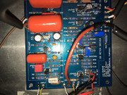
Thanks,

Jeff

Look back at my post.  You're measuring DC resistance, which will be far less than the AC Impedance on the spec sheet.  I'll check those against a working one monday, but you don't seem to have any damaged windings.  Any shorts between these windings?

Mike
 
Hi Mike,

I checked for continuity between the different windings and was not getting any beeping on the continuity test function.  I checked for resistance and was getting readings in the megaohms - is this normal?  Were you able to check a 'good' unit for dc resistance?  I just purchased another one today from your store as I would eventually like to build another unit, but would like to know if I have traced the issue to the output transformer, mostly for peace of mind.

Thanks again,

Jeff
 
jbmacdo3 said:
Hi Mike,

I checked for continuity between the different windings and was not getting any beeping on the continuity test function.  I checked for resistance and was getting readings in the megaohms - is this normal?  Were you able to check a 'good' unit for dc resistance?  I just purchased another one today from your store as I would eventually like to build another unit, but would like to know if I have traced the issue to the output transformer, mostly for peace of mind.

Thanks again,

Jeff

Sounds like it's ok.  I haven't checked, but if you ordered one let's maybe wait and see if the new one works?

Let know.

Mike
 
Hey mike

i hope you (or anybody else!) can help me with this  :-\

I followed the mnats wiring instructions for the rotary switch version.
But when i fire it up the calibration signal is very low in GR mode. The compression is not working at all. Sound is just passed through.

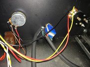
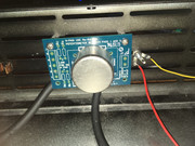
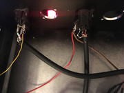
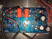
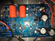
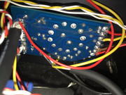
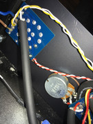
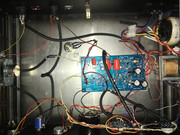
i have uploaded some pictures here of the guts


what do you think is the problem with this ?
any help would be really appreciated!

thanks!

ansgar
 
scott2000 said:
Have you checked all the voltages against the schematic ??? Isn't there one floating around with the voltages??

hey, thanks for your help! there seems to be a probem with Q11, 12 and 13  ???
here are my voltages:
https://s15.postimg.cc/uawwufykp/voltages.jpg
 
I'm sure Mike can help narrow things down a bit for you if you don't figure it out by then..... I did read that the rev A with the rotary has a slightly different approach as the original mnats 1176 rotary??? Something with meter ground??? Not sure what it means without being into it more.....

Sorry I don't know more. Never built one.... and I've seen everything it seems when it comes to solutions to  issues.... surprisingly a lot of bad solder joints too....

 
scott2000 said:
I'm sure Mike can help narrow things down a bit for you if you don't figure it out by then..... I did read that the rev A with the rotary has a slightly different approach as the original mnats 1176 rotary??? Something with meter ground??? Not sure what it means without being into it more.....

Sorry I don't know more. Never built one.... and I've seen everything it seems when it comes to solutions to  issues.... surprisingly a lot of bad solder joints too....

thanks, that would be great to know!
yes i get the feeling my wiring is not 100% correct but i can't really tell what exactly and where. I was quite confused sometimes because they differ on some ways.
Just to give some examples i asked myself:
- X/Y belong to the output xlr, but also the transformer cables blue/red go there, is that correct?
- Is it correct that i don't have to use any capacitors and resistors in the release/attack potentiometers compared to the hairball version?
- Can i use the lorlin 6 pos switch for my ratios (4,8,12, 20 and slam) or do i need the slam switch mod like demonstrated by mnats?
- why can't i get my GR meter to zero with the adjust trim pot
 
weiss said:
thanks, that would be great to know!
yes i get the feeling my wiring is not 100% correct but i can't really tell what exactly and where. I was quite confused sometimes because they differ on some ways.
Just to give some examples i asked myself:
- X/Y belong to the output xlr, but also the transformer cables blue/red go there, is that correct?
- Is it correct that i don't have to use any capacitors and resistors in the release/attack potentiometers compared to the hairball version?
- Can i use the lorlin 6 pos switch for my ratios (4,8,12, 20 and slam) or do i need the slam switch mod like demonstrated by mnats?
- why can't i get my GR meter to zero with the adjust trim pot

Any progress???
 
scott2000 said:
Any progress???

thanks for asking but no. i resoldered all connections in the hope there were some bad solder joints but i had no luck. in fact my 2N3053 overheated for some reason. now i wait for the replacement. it would be nice if someone could help me. i am really starting to become desperate  :(
 
You'll figure it out... I wish I had experience with these but never have tried one....

3053?? That's not ringing a bell for me...

Anyway. I have tried to look at your great pictures but can't make heads or tails of what's what.... All the colors are similar and I usually use white for positive and you used yellow from the input transformer making it more confusing for me....there is a nasty solder blob or something at cr9......lol...

IDK...If you had more detailed pics of the wiring and explanations of what was going where, maybe someone will be able to see something obvious??? I've tried following along with the manual some but my head starts hurting when trying to connect your pics....

I'm not convinced it's a wiring thing but, who knows.....

I hear that just following the original schematics may be a better way as opposed to the manual when in doubt???

You'll get it...
 
scott2000 said:
You'll figure it out... I wish I had experience with these but never have tried one....

3053?? That's not ringing a bell for me...

Anyway. I have tried to look at your great pictures but can't make heads or tails of what's what.... All the colors are similar and I usually use white for positive and you used yellow from the input transformer making it more confusing for me....there is a nasty solder blob or something at cr9......lol...

IDK...If you had more detailed pics of the wiring and explanations of what was going where, maybe someone will be able to see something obvious??? I've tried following along with the manual some but my head starts hurting when trying to connect your pics....

I'm not convinced it's a wiring thing but, who knows.....

I hear that just following the original schematics may be a better way as opposed to the manual when in doubt???

You'll get it...

i really appreciate your help!
yes sorry, my wiring is not self explanatory. i know i should check with the schematic but i have none for the rev A rotary version!  :-\
i checked with the manual without any luck..
 
Wiring for the rotary uses the same points in the schematic...15, 22, and so on.

Have you checked your sidechain voltages here:

http://www.hairballaudio.com/blog/resources/post/fetrack-troubleshooting-guide

#3,4, and 5?

Mike
 
Hairball Audio said:
Wiring for the rotary uses the same points in the schematic...15, 22, and so on.

Have you checked your sidechain voltages here:

http://www.hairballaudio.com/blog/resources/post/fetrack-troubleshooting-guide

#3,4, and 5?

Mike

thanks for your help, mike!
i'll do that when the new parts arrive!
 
Back
Top