[BUILD] 1176 Rev A - Back to the beginning...

GroupDIY Audio Forum

Help Support GroupDIY Audio Forum:

This site may earn a commission from merchant affiliate links, including eBay, Amazon, and others.
Well it would seem your signal is dying in the first amp stage.

Check everything in that area carefully if you haven't already.

Unfortunately, I'm not advanced enough to troubleshoot something that isn't in my hands.
 
I bought a stuffed board and the previous owner forgot to fit r14 a 22k resistor. I've soldered one on, but no improvement.. Could the lack of r14 have caused damage to any onther parts in the preamp circuit, like q3? I've replaced it just in case, and that didn't help either.
 
portix said:
I've just finish the wiring of my rev A. Everything seems to be correct.
When I powered it, the R32 (39 ohm) burn. I 've measure 11V on the resistor. Is it correct?

In fact my local dealer gave me equivalent transistors. He tell me the pinout was the same. After verification, It was false.  ::)
 
Can anyone tell me what "T+C" means, reading from the original urei schematic.

In the Mnats schematic, R45 is located on the ratio switch board. On the original rev A schematic, its called R45 (T+C), and located at the collector of Q9. What gives?

Are they actually in the same PCB place? The original on the left have "wierd circles" at both ends of the T+C resistor.

diff.jpg
 
I have 4 2n3707's with a hfe of 216. Is that good enough or should i spring for hfe of 250 or more like it says. Somewhere I read they shoul be matched, somewhere else it said above 250. Out of 20 none were even close to 250. Wondering why they need to be higher as well. Granted tests were done on a cheap cen tech dmm. Surprise my Fluke 87 doesn't have it. TIA
 
Does anybody know the Mouser part nr. for the three pin header and shorting plug (r44)?
What are the potentiometer value of the output and release knobs? 

Thanks
 
Pieter001,
3-pin header 22-28-4030
Molex 2p jumper 538-15-38-1024
Output Pot 250k
Release 5M
(I just read these pot values off the schematic - if you don't have the schematic it would be wise to get)

ChrioN,
I believe that T&C means test & check at assembly. In mnats schematic, I think he is combining R43& R45 into a single resistor, R43. The main function of this is to make a voltage divider with R42 to set the bias point for Q9, typically midway between the V+ & Grnd.  R45 in mnats schematic serves a different purpose I think - to provide a pulldown for the threshold when none of the push buttons are engaged. Those pushbutton switches (the dpdt half shown on the right side of the schematic) change the compression threshold for different ratios by a voltage divider between the -10 v supply and the Vqbias set with R59. At lower ratios, the dc voltage at the CR2/CR3 diodes is higher, meaning compression begins at lower signal levels.
 
I can't get more than a 0.5dB drop when turning the q bias trimmer. Have tried a bunch of different 2n5457s.
Other than that the unit works flawlessly, passing audio and what not. Have looked through the wiring and all seems correct.
Components are most definitely correct.
What to do?
 
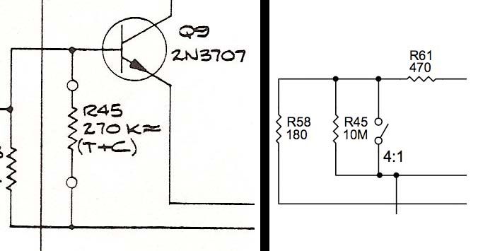
I think you would want the GR off for setting the Qbias, which is pad 22 grounded. Pad 22 is the connection to C17, which is the sidechain input. Any signal passed to the sidechain is rectified into a dc voltage and added to the Qbias voltage, which you do not want when setting the bias.
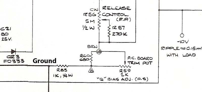
Looking at the schematic, when you adjust Qbias, you are setting the bias ('normal') control voltage (cv) to the FET. If the trimmer is all the way left, the voltage is 0v. All the way right, it is something negative, maybe -3v. The more positive the cv, the more the FET will attenuate the signal (The FET is in a voltage divider with R5).  So, when you set the Qbias, you are setting the cv up from negative until the FET just starts to attenuate your input signal.
Debugging... measure your voltages around the Qbias trimmer and see that the cv is changing as expected as you turn it. If it is turned all the way left on the schematic, the cv on the FET should be near ground and attenuating significantly...
 
dmp, I don't know if what you're saying is applyable to the way I'm biasing my unit.
I'm doing it the same way the original rev a did it. Its a little bit different, not connected to -10v.
Other rules may apply? (actually I have tried both methods, I don't thing the result differed)

reva.jpg
 
Right oh, I was looking at mnats schematic.
In the schematic you are looking at the -10v comes through the ratio switch bank, eh R64, etc...,  and comes back down to the tie point of the 18 on your pic. The voltage at point 18 should be negative and the trimmer should change it.
Interestingly, the original rev A schematic S/N 101-125, which is the schematic before the one you showed, has the right side of the trimmer connected to the -10v supply after a resistor. The one you show, S/N 125-225, doesn't, but then the rev B does again.
 
Ok. Measuring at 18, I get -1.75 to -2.45 with a 2k trimpot (R59). No 1dB drop.  :-\
Also, the output level of the unit does not change when I trim R59.
 
The voltage at 18 should also be at the R7/R6 connection, which is the base of the FET. It could be that there is a problem in the wiring through the release pot... but assuming it is fine, then the problem is at the FET attenuator. It could be that you do not have enough adjustment room for the cv with the qbias trimmer circuit you are using and the particular FETs you have. Or a bad solder or component in this area?
The way the FET attenuator works is that the FET has an effective resistance as the cv increases. Starting out at -2.45 v, the FET resistance is very high (over 1Meg for the ones I measured). It is a simple voltage divider formed with R5 (27k) and the FET. So the GR dB = 20*log10(Rfet/(Rfet+R5)). For the FETs I measured, the resistance dropped to around 100k when the cv got up to ~-1.75, which would be about 2-3 dB of GR. 
 
Thanks for the reply.

Measuring dc voltage at the R7/R6 junction, the voltage fluctuates -0.8v to -1.4v. wierd behavour. Voltage do change when trimming R59.
I also noticed another problem. I only get signal from the positive output of the output transformer. Almost zero vac on the negative.
This might be connected to the q bias problem, but I'm too thick to see that.
VU meter readings are wierd too, 0.4vac on + to gnd, 1.2vac on - to gnd...

everything is quadrople checked
 
I don't see how the output transformer would be related. And I don't really understand the problem.
I can only suggest rechecking all the components around the FET trying to isolate where the problem is. You can pull out components to simplify things until you start seeing things behaving as you expect them to. For instance, pull C5 & C6 and just look at the FET attenuation with the Qbias trimmer.
Debugging can be VERY frustrating. try to keep your patience, take a break, come back to it. I had one resistor value wrong when I built my 1176, 560 ohms instead of 560 kohms. I went around and around trying to find that problem.
 
Yes I know.
In later builds I have become a little bit better on taking things slow, and don't freak out by the - sometimes - overwhelming debugging.
I'll try to isolate the problem.

But the transformer issue is still a mystery.
 
I rearanged the q bias adjustment to the one in the mnats schematic. it works perfectly.

Will that q bias methods of rev A and rev D make any changes in the behaviour of the limiter?
 
Great!
I think the Qbias setting is just a virtual ground for the sidechain control voltage... it needs to be a few volts below zero for the fet to work properly, but it is a stable constant voltage, i.e. should not effect the sound. After all in either circuit, the cv sees the qbias through the release resistance, which is >200k, while the Qbias voltage is connected to power / ground through ~2k. With two orders of magnitude difference, changes in the cv shouldn't create ripple in the Qbias voltage.
 

Latest posts

Back
Top