[BUILD] 1176LN Rev D DIY

GroupDIY Audio Forum

Help Support GroupDIY Audio Forum:

This site may earn a commission from merchant affiliate links, including eBay, Amazon, and others.
Hello Mike, well how to tell you: 
First thank you for your support
Second i'am an idiot the answer was in my question!As usual!
Because I measured and listened through my souncard and never doubt about it,actually it works well, but the issue came from it's output impedance !!
Indeed with my friend we tested the unit with his generator and scope and guess what the unit behave perfectly as expected!
His generator has a an impedance  about 50 ohms and i followed the test as you mentionned me earlier and everything went perfect!
Then he explained me things about impedance conflict (wich i 'am not able to translate due to my poor english)and this is where the issue is!!
When the unit was finished and calibrated  i rushed into a rough listenning without thinking to what i was doing.So stupid !
Third of course it sounds awesome( surely from the beginning) and you and mnats had done a great job!Keep going!!
So thanks again Mike and sorry if i annoyed you !!
Christophe
PS: sorry for my french gibberish and next moth i'll try myself with the Rev A!
 
Hey group. I posted here a couple moths back about problems with my Rev D kits and I'm still unable to get them up and running again.

Basically, I had them both fire up immediately upon completion, voltage on the main PCB tested good and I was using them when they both powered down in front if me and I haven't been able to get them back up since.

I have searched for answers on this forum, tried various new fuses, replaced both IEC outlets, rebuilt both power supplies on each PCB, purchased and replaced both power transformers and power/meter assemblies, and populated and tested the power supplies on a pair of Rev A PCBs I have. I have a new pair of power/meter switches and PCB boards on the way from Hairball and I will swap those in or keep them for the two Rev As I plan to build if I get these running. But so far ive run out of any other ideas.

I measure 124 volts at the IEC and at the power transformer where it connects to the power switch, but I measure 0 volts coming into the main PCB at all three points and I get nothing from the meter.

I am at a loss. If anybody can think of anything I am missing I would be more than willing to give it a shot.
 
If you have same problem on both units, it's probably same mistake what you did with connection on some point.
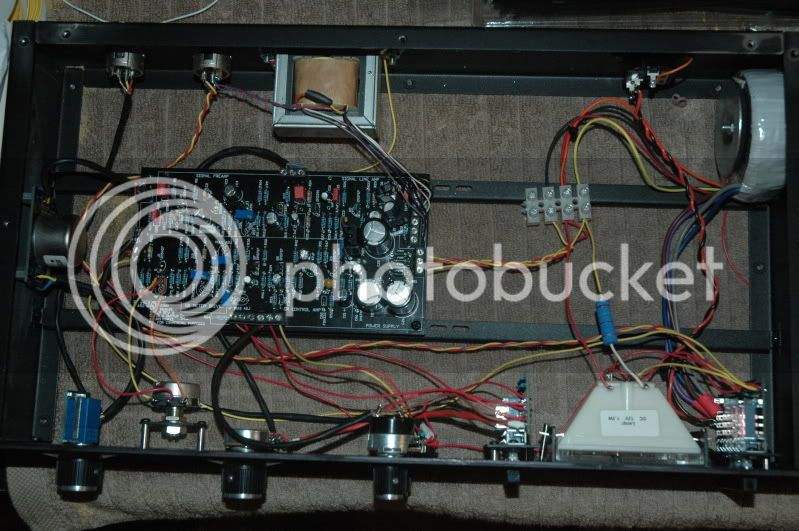
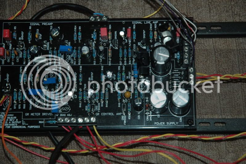
I think the best way it be a good set of photos of inside both units - it's truly hard to tell anything from the head, not seeing circuit.
 
Here is a shot of one of them. The other I disassembled to rebuild the power supply. I can post a picture of it when I put it back together.
DSC_0085.jpg


DSC_0088.jpg


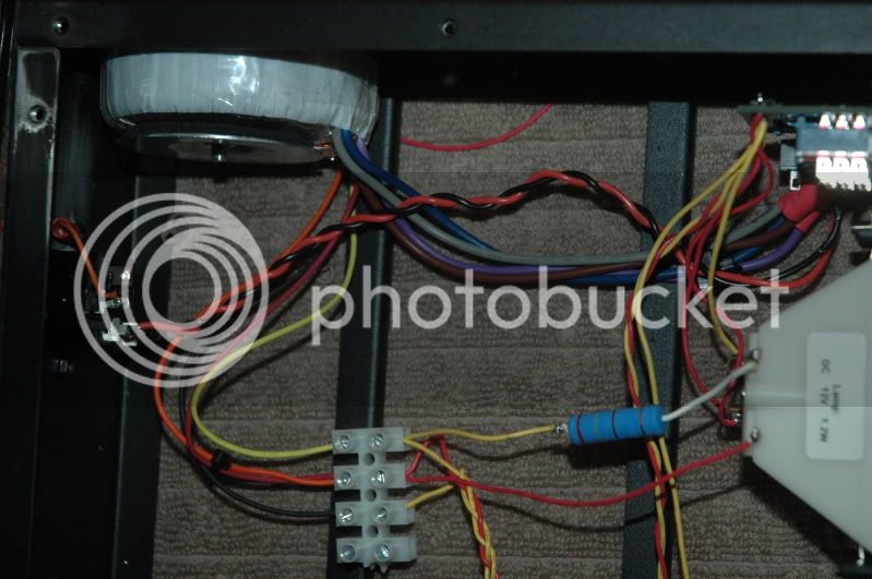
DSC_0089.jpg
 
PeterL said:
Here is a shot of one of them. The other I disassembled to rebuild the power supply. I can post a picture of it when I put it back together.
What manufacturer and type is the mains transformer? Looks like primaries/secondaries connected backwards.
 
The power transformer is an Avel Lindberg Y236106, from Hairball for this kit. Blue and Violet together and Brown and Grey together for primary's for 120V. Red and orange secondary tied together for center tap.
 
Did You measured secondary windings without any load?
Did You tried to power up without VU meter connection?
 
I measure 123v at the IEC outlet and at the switch, but 1.5 at each secondary. Unless I have done something else wrong, this is the third power transformer I have tried, new out of the box. Maybe my switch is bad?
 
Transformer is good i think. Of course you've measured on AC?!? Sorry - but sometimes happens:)
Probably switch is good, maybe you've connected wrong something ?
Try to unsolder secondary windings and measure bare wires.
Good photo on wires connection will be helpfull.
 
You should measure voltage between black and red and between orange and yellow. This should give you +/-25V per side.
 
In76d, I appreciate your help, I am just a little new to this stuff and I'm trying my best. By measuring voltage between black and red and between orange and yello, do you mean joining these pairs and measuring their respective voltages? I just tried that and Black and red together read 81vAC and Orange and Yellow read 82vAC.
 
First measure secondary windings well.
Put the BLACK cable from the multimeter to the BLACK on your secondary.
Put the RED cable from the multimeter to the RED on secondary.
Read the voltage.
Put the BLACK cable from the multimeter to the ORANGE on your secondary.
Put the RED cable from the multimeter to the YELLOW on secondary.
Read the voltage.
 
Everyone is "new" in something different.
It's not a shame to ask.
Please hurry, because i need go to sleep (but don't kill yourself by voltage) :D

I hope that youre alive :)
I'm going to sleep.
If you measure different voltages, that you should have -  leave it for now, because you can damage something more.
Your problem is probably on a point where you conected secondary windings.

Your connection:

YELLOW (one side)
RED and ORANGE (center)
BLACK (other side)

Should be:

YELLOW (one side)
BLACK and ORANGE (center)
RED (other side)

I hope it will works now!

Goodnight
 
ln76d said:
Everyone is "new" in something different.
It's not a shame to ask.
Please hurry, because i need go to sleep (but don't kill yourself by voltage) :D

I hope that youre alive :)
I'm going to sleep.
If you measure different voltages, that you should have -  leave it for now, because you can damage something more.
Your problem is probably on a point where you conected secondary windings.

Your connection:

YELLOW (one side)
RED and ORANGE (center)
BLACK (other side)

Should be:

YELLOW (one side)
BLACK and ORANGE (center)
RED (other side)

I hope it will works now!

Goodnight

I don't think so. The transformer wiring seems correct to me...
Check the attachment if you're not sure.
 
got busy but am back at it once again. (previous posts on page 136ish)

So trying to remember...

Q13 is a problem: I read -1.7 VDC on the top pin. (board oriented with mnats logo in bottom left corner)

[these are  npn's so I guess that is the emitter because the typical voltage schematic reads -1.63vdc and it's the arrow pointing away?]

I get +11.11 vdc on the center pin. (is that the base?)

and on the bottom pin I get -0.9 vdc (or is this the base b/c the schematic says the base is -1.04 vdc and the collector should be +9.75 vdc?)


I'm also getting the same +11 vdc on both ends of R74 which I was told was no good.

I would appreciate the visual/kinesthetic/ hands-on lesson about the schematic interpretation and also advice on what to do about R74 and Q13. thanks fellas
 
Hank Dussen said:
I don't think so. The transformer wiring seems correct to me...
Check the attachment if you're not sure.

So you are wrong  :)

Look on photo of Avel Lindberg Y236106 (which PeterL use) which i posted above.
From secondary windings description from photo:

BLACK - 0V
RED - 25V
ORANGE - 0V
YELLOW - 25V

How should be connected transformer in this circuit?
Center tapped?
Look on the last figure from your picture.
Look on PeterL photos of his connection.
Do You see what i saw?
 

Latest posts

Back
Top